


22 RV53i & RV53e Operation and Installation Manual
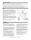
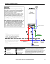
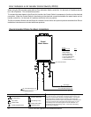
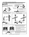
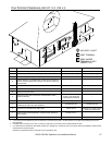
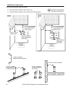
Recommended Piping for Basic Installation
G
a
s
S
u
p
p
l
y
3
/
4
"
C
o
l
d
W
a
t
e
r
S
u
p
p
l
y
L
i
n
e
3/4" Hot Water Supply Line
Rinnai
Water Heater
Rinnai
Equipment List
Rinnai
Water Heaters
RIK-KIT (Optional)
(3/4" Fittings Include:
2 Unions, 2 Ball Valves,
2Drain Valves and
1 Pressure Relief Valve.)
QTY
1
1
3
/
4
"
G
a
s
C
o
n
n
e
c
t
i
o
n
For Building Fixtures
Pressure Relief Valve
3/4" Ball Valve
3/4" Union
Check Valve
S
Pressure Regulator
Circulating Pump
Solenoid Valve
Boiler Drain Valve
KEY
This is not an engineered drawing. It is intended only as a guide and not
as a replacement for professionally engineered project drawings. This
drawing is not intended to describe a complete system. It is up to the
contractor/engineer to determine the necessary components and
configuration of the particular system being installed. This drawing does
not imply compliance with local building code requirements. It is the
responsibility of the contractor/engineer to ensure installation is in
accordance with all local building codes. Confer with local building
officials before installation.
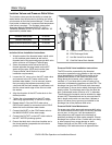
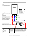
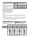
Error Indication or Air Handler Control Switch (RV53i)
When using the Rinnai water heater with an Error Indication Switch, switch No. 4 in the bank of 8 switches should
be in the off position. This is the default position.
To connect the water heater to the Rinnai Air Handler, the Control Switch is necessary to function as the electrical
connection. When the Control Switch is functioning as the electrical connection between the water heater and air
handler, switch No. 4 in the bank of 8 switches should be in the on position.
The Error Indication Switch and the Rinnai Air Handler Control Switch are optional products available from Rinnai.
Installation instructions are included with these products.