


20 Manual - Rinnai Condensing Water Heaters
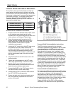
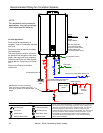
Isolation Valves and Pressure Relief Valve
Water Piping
The isolation valves provide the ability to isolate the
water heater from the structure’s plumbing and allow
quick access to flush the heat exchanger. Check with
local codes to determine if a pressure and temperature
relief valve is required. The included valves meet
American National Standard (ANSI Z21.10.3) /
Canadian Standard (CSA 4.3) and are ANSI/NSF 65
approved for potable water.
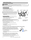
Isolation Valves Installation Instructions:
1. Wrap the ends of the threaded water inlet & outlet
on the tankless water heater,as well as the
threaded end of the approved pressure relief valve
with a minimum of 5 wraps of Teflon® tape.
2. Screw the pressure relief valve into the 3/4”
threads opposite the wing handle on the HOT
water service valve. (RED drain handle) (see
Pressure Relief Valve Section for proper
installation requirements)
3. Loosen the 3/4” union nut on the HOT water valve
and connect to the HOT water outlet on the
tankless water heater. If nut is removed, ensure
that you realign the tailpiece accurately to the
valve and that the black washer is positioned such
that the raised metal edge of the valve is inside
the washer.
4. Align the direction of the HOT water drain to the
desired position.
5. Tighten the union assembly to the HOT water
valve using approximately 15 foot lbs of torque.
6. Repeat steps 3-5 for the COLD water valve.
(BLUE drain handle) for connection to the COLD
water inlet on the tankless water heater.
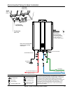
7. Connect the INLET on the COLD water valve to
the MAIN SOURCE of the water supply.
8. Connect the OUTLET on the HOT water valve to
the HOT WATER plumbing system.
9. Ensure that both drain valve lever handles are in
the closed position (perpendicular to the drain
portion of the body).
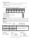
Isolation Valve (Cold)
107000082
Isolation Valve (Hot)
107000084
Pressure Relief Valve (PRV)
107000085
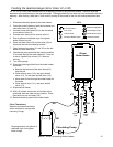
Pressure Relief Valve Installation Instructions:
The PRV must be connected by the threaded
connection opposite the wing handle on the hot water
valve (designated by the RED drain handle) or the
threaded connection on the side of the relocation
fitting above the hot water valve. Installation must
maintain a ¾” port size with no shut off valve or line
restriction in-between the appliance and the PRV. The
discharge line from the PRV should pitch downward
and terminate 6” above drains where discharge will be
clearly visible. The discharge end of the line shall be
plain (unthreaded) and a minimum of ¾” in diameter.
The discharge line material must be suitable for water
at least 180º Fahrenheit and can be no more than 30
feet in length and contain no more than 4 elbows or
bends. No valve of any type may be installed in the
discharge line of the pressure relief valve.
Pressure Relief Valve Maintenance:
For proper care of this approved pressure relief valve,
it is recommended that the valve is manually operated
once a year. In doing so, it will be necessary to
take precautions with regard to the discharge of
potentially scalding hot water under pressure. Ensure
discharge has a place to flow. Contact with your body
or other property may cause damage or harm.
Please note that only the PRV in this package is
certified by CSA International as an approved item.
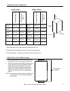
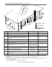
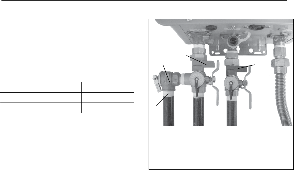
A Pressure Relief Valve (PRV)
B PRV Discharge Outlet
C Hot Ball Valve Drain Handle
D Cold Ball Valve Drain Handle
A
B
C
D