


INSTALLATION – SOLAR CONTROL UNIT
24
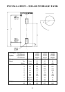
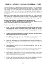
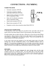
The solar control unit is designed to be mounted on the side of the solar storage
tank, with its location above and offset from the cold water inlet. The solar control
unit, supplied with a 1.8 metre power cord, requires a 220 – 240 V general power
outlet (GPO) located within 1.2 metres of its installation. If the installation is
outdoors, the power outlet must be weatherproof (refer to “Connections – Electrical”
on page 32).
Note: Care must be taken when mounting the solar control unit to the side of the
solar storage tank. Damage to the cylinder as a result of mounting the solar control
unit to the jacket will void the warranty (refer to “Saddling - Pipe Work” on page 20).
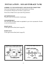
SOLAR CONVERSION OF A RHEEM ELECTRIC WATER HEATER
To connect the solar cold and hot pipes and mount the solar control unit on a
Rheem electric water heater (without a raised solar hot inlet):
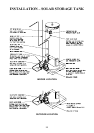
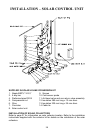
Numbers in parentheses refer to items on diagram on page 26.
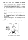
· Fit the 5 way tee (2) to the cold water inlet of the solar storage tank. Ensure
the rounded tube (snorkel) is orientated upwards when inserted into the solar
storage tank, the cold sensor housing is orientated horizontally to the front of
the solar storage tank and the solar cold outlet is orientated vertically upwards.
· Connect the DN15 preformed pipe (4) to the solar cold outlet connection, using
the compression nut (5) and olive (6) provided.
· Fit a BSP½” x G½” nipple (1) to the outlet of the circulator (7) in the solar
control unit (8) (ensure the compression end of the nipple is exposed).
· Locate the solar control unit (8) by connecting the DN15 preformed pipe (4) to
the nipple on the inlet of the circulator (7) using the compression nut (5) and
olive (6) provided.
· Secure the solar control unit (8) to the solar storage tank using the four
screws (9) provided.
· Connect the solar cold pipe (to the collector) to the nipple (1) on the outlet side
of the circulator (7) using the compression nut (5) and olive (6) provided.
· Insert the cold sensor probe (10) into the cold sensor housing on the 5 way
tee (2), ensuring the ‘O’ ring is in position on the probe. Lock it into position
with the locking washer and clip provided.
· Connect the hot sensor lead (from the solar collector installation) to the hot
sensor cable connector at the underside of the solar control unit (8).