


5
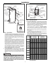
The pressure rating of the relief valve must not exceed 150 psi
(1,034 kPa), the maximum working pressure of the water heater
as marked on the rating plate. The BTUH Rating of the relief valve
must not be less than the input rating of the water heater as in-
dicated on the rating label located on front of the heater
(1 watt = 3.412 BTUH).
Connect the outlet of the relief valve to a suitable open drain so that the
discharge water cannot contact live electrical parts and to eliminate
potential water damage. Piping used should be of a type approved for
hot water distribution. The discharge line must be no smaller than the
outlet of the valve and must pitch downward from the valve to allow
complete drainage (by gravity) of the relief valve and discharge line. The
end of the discharge line should not be threaded or concealed and
should be protected from freezing. No valve of any type, restriction or
reducer coupling should be installed in the discharge line.
4. TO FILL WATER HEATER — Make certain drain valve is completely
closed. Open shut-off valve in cold water supply line. Open each hot
water faucet slowly to allow air to vent from the water heater and piping.
A steady flow of water from the hot water faucet(s) indicates a full water
heater.
Tank MUST BE full of water before power is turned on. Heating
element(s) WlLL BE DAMAGED if energized for even a short time
while tank is dry. The water heater’s warranty does not cover
damage or failure resulting from operation with an empty or
partially empty tank. (Reference is made to the limited warranty for
complete terms and conditions.)
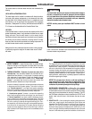
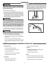
5. ELECTRICAL CONNECTIONS — A separate branch circuit with copper
conductors, overcurrent protective device and suitable disconnecting
means must be provided by a qualified electrician. All wiring must
conform to local codes or the latest edition of National Electrical Code
ANSI/NFPA 70, or in Canada, the Canadian Electric Code.
In order to conform with U.L. requirements, it is absolutely necessary
that the Junction Box Kit be installed per figure 3 above. An opening for
either 1/2” or 3/4” electrical fitting is provided for field wiring connections.
Refer to Figure 3.
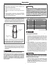
The voltage requirements and wattage load for the water heater is
specified on the rating plate on the front of the heater.
Table 1, below, recommends minimum branch circuit sizing based on
the National Electric Code. Refer to the wiring diagram marked on the
back cover of this manual for field wiring connections.
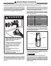
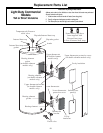
Installation
R
E
L
I
E
F
V
A
L
V
E
COL
D
HO
T
Heat trap
6" (15.24 cm)
minimum
6" (15.24 cm)
air gap
Union
Temperature
&
Pressure
Relief Valve
Anode
Union
Hot
water outlet
to fixtures
Jacket access
panels
Drain valve
Auxiliary
catch pan
2" (5 cm)
maximum
Relief valve
discharge line to
suitable open drain
Thermal
expansion tank
(if required)
Electrical
junction box
(use only copper
conductors)
To
cold water
supply
Shut-off
valve
Heat trap
6" (15.24 cm)
minimum
Figure 2. — Typical Installation
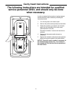
WARNING
!
WARNING
TANK MUST BE FULL
OF WATER BEFORE
HEATING ELEMENTS
ARE ENERGIZED. SEE
INSTALLATION
INSTRUCTIONS
Figure 3. — Water Heater Junction Box.
Table 1. — Branch Circuit Sizing and Wire Size Guide Based on
N.E.C. ANSI / NFPA 70
P
Recommended Over
Total h
Current Protection Copper Wire Size -
Water a
(Fuse or Circuit Breaker) AWG Based on N.E.C.
Heater s
Amperage Rating Table 310-16 (75°C.)
Wattage e 208V 240V 277V 480V 208V 240V 277V 480V
3,000
12020151512121414
3 20 20 --- 15 12 12 --- 14
4,000
12525201510101214
3 25 25 --- 15 10 10 --- 14
4,500
13025251510101014
3 30 25 --- 15 10 10 --- 14
5,000
13030251510101014
3 30 30 --- 15 10 10 --- 14
5,500
1 35 30 25 15 8 10 10 14
3 35 30 --- 15 8 10 --- 14
6,000
140353020 8 8 1012
3 35 30 --- 15 8 10 --- 14
8,000
150454025 8 8 8 10
3 45 40 --- 20 8 8 --- 12
9,000
1 --- 50 45 25 --- 8 8 10
3 50 45 --- 25 8 8 --- 10
10,000
1 --- --- 50 30 --- --- 8 10
3 --- 50 --- 25 --- 8 --- 10
11,000
1 --- --- 50 30 --- --- 8 10
3 --- 50 --- 25 --- 8 --- 10
12,000
1 --- --- --- 35 --- --- --- 8
3 --- --- --- 30 --- --- --- 10
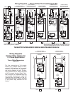
Three (3) sheet metal screws removed
from "factory installed" junction box.
Cover and Label
Insert Electrical Leads
through Snap Bushing into
Junction Box
Leads from water heater.
Either 2, 3 or 4 wires
Snap
Bushing
Ground
Screw
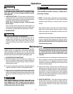
Vacuum Relief Valve
(Not Supplied)
If required, install per local codes
and valve manufacturer’s
instructions.