


1. INSPECT SHIPMENT — Inspect the water heater for possible damage.
Check the markings on the rating plate of the water heater to be certain
the power supply corresponds to that for which the water heater is
equipped.
2. THERMAL EXPANSION — Determine if a check valve exists in the
inlet water line. It may have been installed in the cold water line as a
separate back flow preventer, or it may be part of a pressure reducing
valve, water meter or water softener. A check valve located in the cold
water inlet line can cause what is referred to as a ”closed water
system”. A cold water inlet line with no check valve or back flow
prevention device is referred to as an ”open” water system.
As water is heated, it expands in volume and creates an increase
in the pressure within the water system. This action is referred
to as ”thermal expansion”. In an ”open” water system, expanding
water which exceeds the capacity of the water heater flows back
into the city main where the pressure is easily dissipated.
A ”closed water system”, however, prevents the expanding
water from flowing back into the main supply line, and the result
of ”thermal expansion” can create a rapid, and dangerous pres-
sure increase in the water heater and system piping. This rapid
pressure increase can quickly reach the safety setting of the re-
lief valve, causing it to operate during each heating cycle. Ther-
mal expansion, and the resulting rapid, and repeated expansion
and contraction of components in the water heater and piping
system can cause premature failure of the relief valve, and pos-
sibly the heater itself.Replacing the relief valve will not correct
the problem!
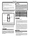
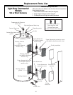
The suggested method of controlling thermal expansion is to install
an expansion tank in the cold water line between the water heater and
the check valve. (refer to Figure 2.) The expansion tank is designed
with an air cushion built in that compresses as the system pressure
increases, thereby relieving the over pressure condition and elimi-
nating the repeated operation of the relief valve. Other methods of
controlling thermal expansion are also available. Contact your in-
stalling contractor, water supplier, or plumbing inspector for additional
information regarding this subject.
NOTICE!! Do not apply heat to the hot or cold heat trap fittings. If
sweat connections are used, sweat tubing to adapter before fitting
adapter to water connections on heater. Any heat applied to the water
connections will permanently damage the heat trap fittings.
WATER SUPPLY CONNECTIONS — Refer to Fig. 2 for suggested
typical installation. The installation of unions or flexible copper connectors
is recommended on the hot and cold water connections so that the water
heater may be easily disconnected for servicing if necessary. The HOT
and COLD water connections are clearly marked and are 3/4” NPT on all
models. Install a shut-off valve in the cold water line near the water
heater.
3. RELIEF VALVE — A new combination pressure and temperature
relief valve, complying with the Standard for Relief Valves and
Automatic Gas Shutoff Devices for Hot Water Supply Systems,
ANSI Z21.22, must be installed in the opening provided and
marked for the purpose on the water heater. (Refer to Fig. 2.) No
valve of any type should be installed between the relief valve and
the tank. Local codes shall govern the installation of relief valves.
4
The location chosen for the water heater must take into consideration the
following:
LOCAL INSTALLATION REGULATIONS
This water heater must be installed in accordance with these instructions,
local codes, utility company requirements or, in the absence of local codes,
the latest edition of the National Electrical Code. It is available from some
local libraries or can be purchased from the National Fire Prevention
Association, 1 Batterymarch Park, Quincy, MA 02269 as booklet ANSI/NFPA
70. In Canada, use the latest edition of the Canadian Electric Code.
LOCATION
Locate the water heater in a clean dry area as near as practical to the area of
greatest heated water demand. Long uninsulated hot water lines can waste
energy and water. Place the water heater in such a manner that the
thermostat and element access panels can be removed to permit inspection
and servicing such as removal of elements or checking controls. The water
heater and water lines should be protected from freezing temperatures. Do
not install the water heater in outdoor, unprotected areas.
Make certain the floor underneath the water heater is strong enough
to sufficiently support the weight of the water heater once it is filled
with water.
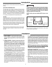
The water heater should not be located in an area where leakage of
the tank or connections will result in damage to the area adjacent
to it or to lower floors of the structure. Where such areas cannot be
avoided, it is recommended that a suitable catch pan, adequately
drained, be installed under the water heater.
NOTICE: Auxiliary catch pan installation MUST conform to local
codes.
Catch Pan Kits are available from the distributor or store where
the water heater was purchased.
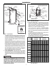
Introduction
A — Diameter of water
heater plus 2" (5 cm)
min.
B — Maximum 2" (5 cm)
To open drain, line should
be at least
3
/
4
" (1.9cm) ID
and pitched for proper
drainage.
A
B
Figure 1. — Auxiliary Catch Pan
CAUTION
!
Installation