


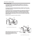
ELECTRICAL CONNECTIONS
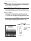
Figures 9 and 10 are general wiring diagrams.
For a maintaining temperature boiler, Figure 9
should closely match your system. For cold start
boilers your wiring may resemble Figure 10, but will
vary depending on the boiler type and controls or
relays used. It is not possible to list all wiring
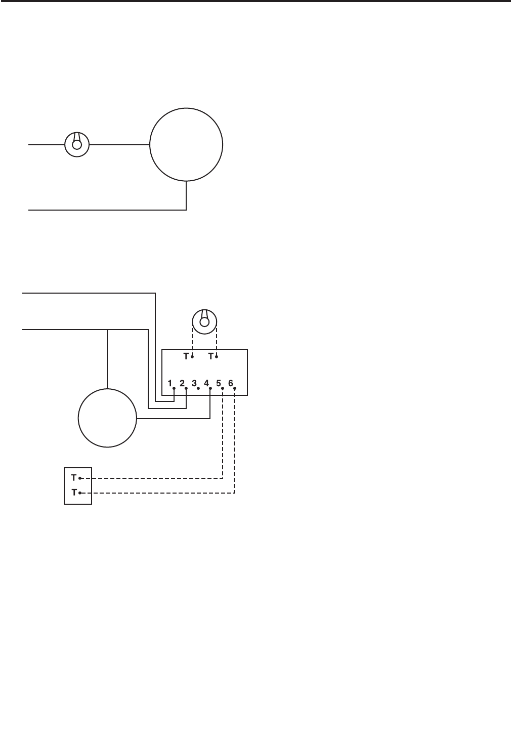
variations here. When connecting to a cold start
boiler, always remember that in principle an indirect
water heater operates as another heating zone. The
difference is when the indirect water heater calls for
heat, the indirect water heater circulator must start
rather than opening a zone valve; the system
circulator stays off; and the boiler must light to
reach high limit.
WIRING NOTES:
1. Dashed lines indicate low voltage (24 VAC)
2. Use jumper wire between terminals #1 and #3 on
R845 relay
THERMOSTAT SPECIFICATIONS:
Thermostats can operate at low or line voltages.
24 volt N/A
120 volt 8 amp
240 volt 5 amp
This equipment must be properly grounded to
prevent a potential shock hazard, and to reduce
deterioration of the anode due to electrolysis. Refer
to local electrical codes and ordinances.
Page 11
SECTION IV: INSTALLATION (cont.)
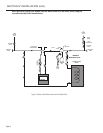
Figure 9: Boiler Maintaining 180°F
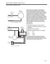
Figure 10: Cold Start Boiler
Figure 9: Boiler Maintaining 180°F
Indirect
Aquastat
Indirect
Circulator
L1 HOT
120 VOLT
L2 NEUTRAL
Figure 10: Cold Start Boiler
L1 HOT
120 VOLT
L2 NEUTRAL
Indirect
Circulator
Indirect
Aquastat
Burner
Control
R845 Relay
or Equivalent