


32
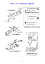
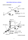
MULTIPLE INSTALLATIONS
A multiple installation of Rheem water heaters on a single manifold or multiple
manifolds is possible, using the Rheem Equa-Flow
®
manifold system, where
large volumes of hot water are required. The Equa-Flow principle will function
with water heaters in line, around a corner or in rows back to back (refer to the
diagrams on page 33).
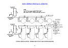
The cold water and hot water manifolds must be designed to balance the flow
from each water heater. To achieve this, there are basic installation
requirements and principles which must be followed:
1. The maximum number of water heaters in a bank should be 8, however
several banks of water heaters can be installed.
2. The hot water line from the manifold must leave from the opposite end to
which the cold water line enters the manifold.
3. The water heaters must be of the same model.
4. The cold water line, cold and hot headers and hot water line must be sized
to meet the requirements of both AS/NZS 3500.4 and the application.
5. A non return valve, isolation valve and if required a pressure limiting valve
and expansion control valve, must be installed on the cold water line to the
system.
6. A full flow gate valve or ball valve (not a stop tap, as used on a single water
heater installation) must be installed on both the cold water branch and hot
water branch of each water heater.
7. Non return valves or pressure limiting valves must not be installed on the
branch lines to the water heaters.
8. All fittings, valves and branch lines must be matched sets all the way along
the manifold.
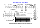
9. Sufficient space must be left to enable access, servicing or removal of any
water heater. Outdoor 631 265 models must be spaced at minimum
920 mm centres to provide the required clearance between flue terminals.
10. The temperature pressure relief valve drain line from each water heater can
terminate at a common tundish (funnel) with a visible air break at each drain
discharge point (refer to the diagram on page 33 and to “Relief Drain Line”
on page 27).
Refer to the diagrams on pages 33 to 36 for installation and plant layout details.