


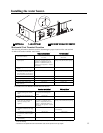
17
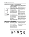
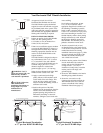
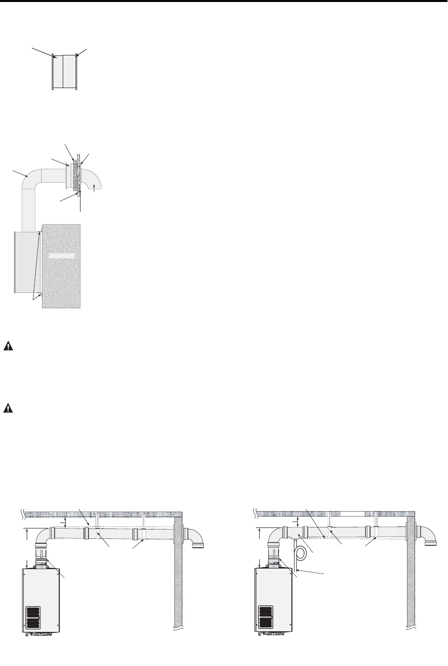
Vent Horizontal Wall Thimble Installation
An approved 4 inch (10 cm) Vent
Horizontal Wall Thimble must be used.
The Wall Thimble requires mechanical
support from the wall sufficient to support
any incidental loads on the system. If the
wall is not sufficient enough to support the
Wall Thimble, then appropriate additional
framing and/or blocking is required.
INSTALLATION PROCEDURE:
Prepare an opening for the Wall Thimble
in the wall. The opening must be
6-1/2 inches (16 cm) in diameter for a
4 inch (10 cm) vent system.
If there are not sufficient support members
to secure the Wall Thimble or if there is a
semirigid foam insulation layer under the
sheathing, appropriate fasteners must be
used to secure the Wall Thimble to the
support members.
The Wall Thimble is designed to adapt to
any wall thickness from 3-1/2” (9 cm) to
6” (15 cm) thick. If the wall is thicker
than 6” (15 cm) the Wall Thimble may be
extended using a piece of 6” (15 cm)
diameter snaplock or welded seam
galvanized pipe up to 6” (15 cm) long.
Select the larger diameter half of the Wall
Thimble for the outside of the wall.
● Apply a continuous bead of high
quality silicone or silicone/latex caulk
on the inside of the outer flange. This
will be the only weather seal to keep
moisture outside the building. Ensure a
sufficient seal is made.
● Position this portion of the Wall
Thimble into the prepared hole from the
outside. Secure the assembly into the
prepared opening using fasteners as
indicated by sheathing or structural
members, sealing the screw heads with
more caulking.
Use 4 hollow wall anchors, at least
1/8” (.32 cm) in diameter and of
appropriate length for the thickness of
the sheathing, if sheathing is particle
board or other composite material. Use
4 #10x1-1/4” wood screws for plywood,
solid wood sheathing or members. Use
suitable masonry anchors when passing
through solid masonry walls. Reinstall
the decorative sheathing around the
Wall Thimble. This assembly may be
painted to match the exterior decor.
● Attach a screened 4 inch (10 cm)
termination fitting to the female end of
a vent section or slip connector. Use the
method described in the Venting
installation instructions (page 13). Slide
the vent in through the outside of the
Thimble and seal the annular space
with a thick bead of caulk.
● Slide the interior portion of the Thimble
into the inside hole. Be certain the
interior and exterior Thimble halves
overlap at least 1” (2.5 cm). If
insufficient overlap exists, extend the
interior portion with single wall
galvanized pipe.
● Secure the Wall Thimble to the interior
sheathing using suitable fasteners.
● Secure the vent section or slip
connector that protrudes through the
Wall Thimble to the rest of the vent
system as described in the Venting
installation instructions (page 13).
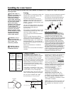
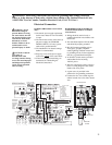
Inner Thimble
Section
Outer Thimble
Section
90° Elbow
Inner Wall
Outer
Wall
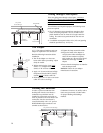
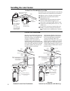
Inner Thimble
Section
Outer Thimble
Section
Vent
Pipe
Water
Heater
Caulk for
weather seal
Outside Wall
90° terminatio
n
with screen
Mounting
Brackets
Side View
Side View
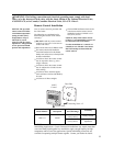
WARNING: Use UL
approved Category III vent
material only. No other
vent material is permitted.
CAUTION: Follow the
vent manufacturers
installation instructions as
design might vary from
manufacturer to
manufacturer.
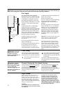
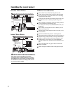
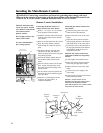
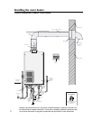
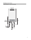
Vent
Adapter
3” (8 cm) Clearance
Support
Hanger
Condensate
Trap
To Drain. Dispose of
condensate in accordance
to local codes
1/4” per foot upward slope
3’
(91 cm)
Max
Vent
Adapter
3” (8 cm) Clearance
Support
Hanger
1/4” per foot downward slope
3’
(91 cm)
Max
Typical Horizontal Termination
w/ ¼” per foot DOWNWARD Slope
Typical Horizontal Termination
w/ ¼” per foot UPWARD Slope