


10
Installing the water heater.
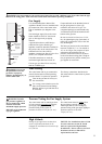
Relief Valve
A new pressure relief valve, complying
with the Standard for Relief Valves and
Automatic Gas Shut-Off Devices for Hot
Water Supply Systems, ANSI Z21.22,
must be installed at the hot water outlet
connection of the water heater at the
time of installation. Local codes shall
govern the installation of relief valves.
For safe operation of the water heater, be
sure that:
● The pressure rating of the relief valve
must not exceed 150 psi, the maximum
working pressure of the water heater as
marked on the rating plate.
● The BTUH rating of the relief valve
must equal or exceed the BTUH input
of the water heater as marked on its
rating plate.
● No valve of any type should be
installed between the relief valve and
the water heater
● Discharge from the relief valve should
be piped to a suitable drain to eliminate
potential water damage. Piping used
should be of a type approved for the
distribution of hot water.
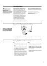
● Hot and cold water lines should be
insulated up to the water heater. Refer
to page 17 for details.
● The discharge line must be NO
SMALLER than the outlet of the valve
and must pitch downward to allow
complete drainage (by gravity) of the
relief valve and discharge line.
● The end of the discharge line should not
be threaded or concealed and should be
protected from freezing. No valve of
any type, restriction or reducer coupling
should be installed in the discharge line.
Notice: Local codes govern the
installation of relief valves. If local codes
require that a temperature and pressure
relief valve should be installed the
manufacturer recommends a type 40XL
Watts T&P relief valve or an equivalent
model be used.
Notice: Manual operation of relief valves
should be performed at least once a year.
Turn off the electrical power and gas
shutoff valve. Lift and release lever on the
relief valve and check the manual
operation of the relief valve. You should
take precaution to avoid contact with the
hot water coming out of the relief valve
and to prevent water damage.
Notice: If the relief valve on the system
discharges periodically, a problem exists
and service to the water system is
required.
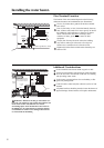
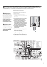
Water Supply Connections Continued.
Install a shutoff valve near the inlet of the
water heater for service and draining
purposes.
DO NOT use pipes with smaller diameters
than the water supply connection of the
water heater.
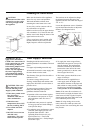
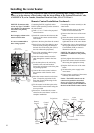
Before connecting the water supply pipe
to the water heater, open the shutoff valve
and clean out sand, debris, air, caulking
material, etc. inside the pipe. Connect to
the water inlet, then check water flow.
Close the shutoff valve and clean the
water filter.
Be sure to connect the water inlet and the
hot water outlet as shown on the water
heater. If reversed, the water heater will
not function.
Installation of unions or flexible copper
connections are recommended on the
HOT and COLD water lines, so that the
water heater may disconnect easily for
servicing if necessary.
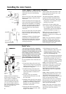
Install a Check Valve between the water
heater and the water shutoff valve. (See
illustration the top left).
The following should be addressed in
regards to the HOT WATER OUTLET:
● Connections between the water heater
and point(s) of use should be as short
and direct as possible.
● DO NOT use lead or plastic pipe.
● To conserve energy and minimize heat
loss, insulation of hot water piping is
recommended. (See Hot and Cold Pipe
Insulation Installation on page 17).
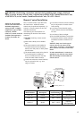
Notice: The flow rate of hot water may
vary when more than two faucets
(appliances, fixtures, etc.) are being used
simultaneously.
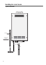
Notice: The pipes MUST be completely
drainable. If the hot water faucets are
located at a point higher than the water
heater, place a drain valve at the lowest
point (see diagram to the left).
Water Filter
Check Valve
Water Inlet
Clean the
Water Filter
Water
Nipple
Air
Relief
Va lv e
Hot
Water
Tap
Drain Valve
Union
Pressure
Relief Valve
Water
Shutoff
Valve
Cold
Water
Supply
Inlet
Hot Water
Supply
Outlet
Relief
Valve
Discharge
Line
Notice: The above illustrates a
pressure only relief valve. If local
codes require a combination
temperature and pressure relief
valve be installed, an extension
piece may be needed. (Refer to
page 16 for example of extension
piece for T&P relief valve
installation.)