


• Fuse type – the “G” in the model number represents Class G fuses.
• Thermostat staging – E models (Immersion thermostat) 24 kW and above (18 kW for 208V), may be ordered
with additional thermostat(s) for staging. Add “S” after fuse type designation. Recommended on 81kW models.
Example: E85-36-G becomes E85-36-GS.
• ASME construction – E models (Immersion Thermostat) may be ordered with ASME certified construction.
Add “A” after capacity designation. Example: E85-36-G becomes E85A-36-G.
• UL Sanitation compliance – all models are UL Sanitation (NSF5) compliant when equipped with the optional
ring seal kits. E(S)50 – AS38355, E(S)85 – AS38356, E(S)120 – AS38357.
• Solid state low water cut-off – E models (Immersion Thermostat) may be ordered with probe type cut-off for
field installation (AP8408).
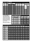
SURFACE MOUNTED THERMOSTATS IMMERSION THERMOSTATS
Tank Capacity In Gallons Tank Capacity In Gallons
50 85 120 50 85 120
ES50-6-G ES85-6-G ES120-6-G E50-6-G E85-6-G E120-6-G
ES50-9-G ES85-9-G ES120-9-G E50-9-G E85-9-G E120-9-G
ES50-12-G ES85-12-G ES120-12-G E50-12-G E85-12-G E120-12-G
ES50-15-G ES85-15-G ES120-15-G E50-15-G E85-15-G E120-15-G
ES50-18-G ES85-18-G ES120-18-G E50-18-G E85-18-G E120-18-G
ES50-24-G ES85-24-G ES120-24-G E50-24-G E85-24-G E120-24-G
ES50-27-G ES85-27-G ES120-27-G E50-27-G E85-27-G E120-27-G
ES50-30-G ES85-30-G ES120-30-G E50-30-G E85-30-G E120-30-G
ES50-36-G ES85-36-G ES120-36-G E50-36-G E85-36-G E120-36-G
ES50-45-G ES85-45-G ES120-45-G E50-45-G E85-45-G E120-45-G
ES50-54-G ES85-54-G ES120-54-G E50-54-G E85-54-G E120-54-G
N/A N/A N/A N/A E85A-81-GS E120A-81-GS
INPUT
KW
6
9
12
15
18
24
27
30
36
45
54
81
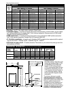
DIMENSIONAL INFORMATION All dimensions shown in English and Metric
MODEL
APPROX. SHIPPING
WEIGHT (LBS.)
NUMBER UNITS
ABCDE
STD. ASME
E(S)50 inches 43-5/8 26-1/4 36-1/4 32 17-1/4 270 lbs. 320 lbs.
mm 1108 667 920 813 438 122 kgs. 145 kgs.
E(S)85 inches 57-11/16 28-1/4 49-1/2 34 18-1/4 350 lbs. 380 lbs.
mm 1465 718 1258 864 464 159 kgs. 172 kgs.
E(S)120 inches 67-5/8 30-1/4 58-3/4 36 19-1/4 430 lbs. 460 lbs.
mm 1718 768 1493 914 489 185 kgs. 209 kgs.
B
D
E
A
4
3
/
4
"
(121mm)
36
1
/
8
"
(917mm)
T&P
5"
(127mm)
SYSTEM SENTINEL
AUTOMATIC
TEMPERATURE
CONTROL
(IMMERSION ONLY)
1
1
/2"
COLD INLET
NIPPLE
1
1
/2"
HOT OUTLET
NIPPLE
C
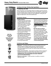
• System Sentinel –
all models employ a diagnostic panel
utilizing light emitting diodes (L.E.D.),
corresponding to the number and
location of each heating element.
L.E.D.’s are energized when the elec-
tric elements are operating. An unlit
L.E.D. pinpoints the exact location of
a non-functioning element, making
element operation diagnosis simple
and positive.
The minimum distance to provide
adequate clearance for protection of
combustible material is 0 inches from
jacket and 18 inches from access door.
However, additional clearance for
accessibility to permit inspection and
servicing such as removing heating
elements or checking controls must be
provided. All models are approved for
installation on combustible flooring.
Heavy Duty Electric continued.
MODEL NUMBERS