


Installing the New Water Heater (cont’d)
13
“Fuel” Conversion Instructions
From Natural Gas To Propane
(L.P.) Gas
Read and follow detailed conversion instructions below and
also in the instruction manual in their entirety before starting
the conversion.
Conversion kit with necessary parts are in a bag attached to
the drain valve.
Step 1. Turn gas control knob “A” to “PILOT”. Depress and
turn “OFF”. (See Figure 4, page 14).
Step 2. Remove outer and inner access doors from water
heater.
Step 3.
Remove burner assembly from water heater and con-
trol by loosening
3
⁄4″ nut “H” holding burner assem-
bly to control. (See Figure 5, page 14). Loosen pilot
tube nut “J” and thermocouple nut “K” at control.
Step 4. Remove screws “D” disengaging manifold from
burner. (See Figure 6, page 14)
Step 5. Remove orifice “E” (See Figure 6, page 14) using
3
⁄8″
wrench. Install orifice marked “L.P.” found in the
bag into manifold. Tighten securely. Secure burner
to manifold with screws “D”.
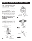
Step 6. Loosen pilot tube nut “F” (See Figure 7, page 14).
Remove orifice “G” and replace with red colored
orifice found in bag. Reinstall nut “F” and tighten
securely.
Step 7.
Make sure all connections are tightened securely,
and reinstall burner assembly into water heater. Po-
sition end of the manifold inside bracket as shown in
Figure 6 on page 14. Reinstall manifold into control
and tighten
3
⁄4 inch nut (“H”) securely. Recheck to see
that end of manifold is still inside bracket as shown
in Figure 6 on page 14. Reinstall pilot tubing and
thermocouple into control. (See Figure 5, page 14)
Step 8. Place screwdriver in slot “B”. (See Figure 4, page
14). Depress and turn counter-clockwise ( ) to
stop. Control screw must be in “IN” position for
propane (L.P.) gas and in “OUT” position for natural
gas. STOP! Read label “For Your Safety” located on
your water heater.
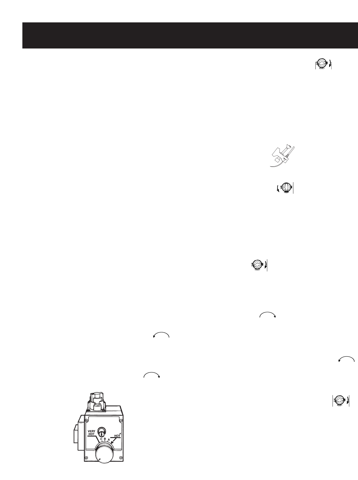
Step 9. Set the thermostat to lowest setting by turning the
water temperature dial clockwise, ( ) to its
lowest temperature setting (with arrow on dial) as
shown.
Step 10. Turn gas control knob clockwise to “OFF”
position. Knob cannot be turned from “PILOT” to
“OFF” unless knob is depressed slightly. DO NOT
FORCE.
Step 11. Wait five (5) minutes to clear out any gas. If you
then smell gas, STOP! Follow “B” in the safety in-
formation on “For Your Safety” label. If you don’t
smell gas, go to the next step.
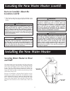
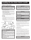
Step 12. Find pilot-follow metal tube from gas control. The
pilot is located in front of the burner. (See Figure 7,
page 14)
Step 13. If you don’t smell gas, turn knob on gas control
counter-clockwise to “PILOT” position.
Step 14. Push in control knob all the way and hold down.
Immediately light the pilot with a match. Continue
to hold control knob in for about one (1) minute
after the pilot is lit. Release knob and it will pop
back up. Pilot should remain lit. If it goes out, re-
peat steps 9 through 12.
• If knob does not pop up when released, stop
and immediately call the local gas supplier.
• If the pilot will not stay lit after several tries,
depress and turn the gas control knob clock-
wise to “OFF”and call the gas supplier.
Step 15. Check for gas leaks with only pilot flame burning
using a soapy water solution, not a match or open
flame. Check for gas leaks at fittings “F”and “G”
(See Figure 7, page 14) and at fitting “J” (See Figure
5, page 14).
Step 16. Make sure temperature adjustment dial is turned
clockwise ( ) in its lowest position (See
Figure 4, page 14).
Step 17. Replace inner and outer doors.
Step 18. At arms length away turn gas control knob to the
full “ON” position. WARNING: Do not use gas
control knob to regulate gas flow. Turn tempera-
ture adjustment dial counter-clockwise ( )
until gas flows to main burner and ignites.
Step 19. With a soapy water solution, not a match or open
flame, check for gas leaks at gas connection “H”.
(See Figure 5, page 14). If gas leak occurs, turn off
immediately by shutting off gas cock at inlet to
control,or by turning gas control knob to
“PILOT” pushing down and turning to “OFF”. Re-
pair gas leak as necessary, and repeat steps 9
through 19.
Step 20. At arm’s length away, set the thermostat to desired
setting. The mark (▼) HOT indicative of approx.
120°F is preferred starting point. Some local laws
may require a lower starting point. If hotter water
is desired see the “Temperature Regulation” sec-
tion in this manual.
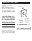
THERMOCOUPLEPILOT BURNER