


A gas line of sufficient size must be run to the water heater.
Consult the current edition of National Fuel Gas Code ANSI
Z223.1, also referred to as NFPA 54 and the gas company con-
cerning pipe size.
There shall be:
– A readily accessible manual shut off valve in the gas supply
line serving the water heater, and
– A drip leg (sediment trap) ahead of the gas control valve to
help prevent dirt and foreign materials from entering the gas
control valve.
– A flexible gas connector or a ground joint union between the
shutoff valve and control valve to permit servicing of the unit.
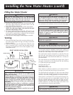
Be sure to check all the gas piping for leaks before lighting the
water heater. Use a soapy water solution, not a match or open
flame. Rinse off soapy solution and wipe dry.
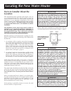
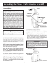
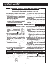
Connecting the gas piping to the gas control valve of the water
heater can be accomplished by either of the two methods shown.
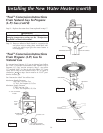
SEDIMENT TRAP
A sediment trap shall be installed as close to the inlet of the water
heater as practical at the time of water heater installation. The
sediment trap shall be either a tee fitting with a capped nipple in
the bottom outlet or other device recognized as an effective sedi-
ment trap. If a tee fitting is used, it shall be installed in confor-
mance with one of the methods of installation shown below.
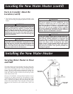
Installing the New Water Heater (cont’d)
Gas Piping
12
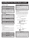
GAS PIPING WITH FLEXIBLE CONNECTOR
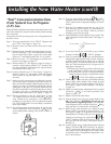
GAS PIPING WITH ALL BLACK IRON PIPE
TO GAS CONTROL
Venting (cont’d)
GAS SUPPLY PIPING
MANUAL SHUTOFF
VALVE
FLEXIBLE GAS CONNECTOR
LABELED AS COMPLYING
WITH ANSI STANDARDS
LOOP
GAS CONTROL
VALVE
DRIP LEG
(Sediment Trap)
CAP
GROUND JOINT
UNION (Optional)
GAS SUPPLY PIPING
MANUAL SHUTOFF
VALVE
BLACK PIPE
GAS CONTROL
VALVE
CAP
GROUND JOINT
UNION
DRIP LEG
(Sediment Trap)
3″ MIN.
3″ MIN.
WARNING
Be sure vent pipe is properly connected to prevent escape of
dangerous flue gases which could cause deadly asphyxiation.
WARNING
Chemical vapor corrosion of the flue and vent system may
occur if air for combustion contains certain chemical vapors.
Spray can propellants, cleaning solvents, refrigerator and air
conditioner refrigerants, swimming pool chemicals, calcium
and sodium chloride, waxes, bleach and process chemicals
are typical compounds which are potentially corrosive.
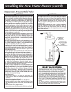
WARNING
Make sure the gas supplied is the same type listed on the model
rating plate. The inlet gas pressure must not exceed 10.5 in.
water column (2.6kPa) for natural gas or 13 in. water column
(3.2kPa) for propane (L.P.) gas. The minimum inlet gas pressure
listed on the rating plate is for the purpose of input adjustment.
WARNING
If the gas control valve is subjected to pressures exceeding
1
⁄
2
pound per square inch (3.5kPa), the damage to the gas con-
trol valve could result in a fire or explosion from leaking gas.
WARNING
If the main gas line shutoff serving all gas appliances is used,
also turn “OFF” the gas at each appliance. Leave all gas appli-
ances shut off until the water heater installation is complete.
WARNING
Use pipe joint compound or teflon tape marked as being
resistant to the action of petroleum [Propane (L.P.)] gases.
WARNING
The appliance and its gas connection must be leak test-
ed before placing the appliance in operation.
WARNING
Contaminants in the gas lines may cause improper operation
of the gas control valve that may result in fire or explosion.
Before attaching the gas line be sure that all gas pipe is clean
on the inside. To trap any dirt or foreign material in the gas
supply line, a drip leg (sometimes called a sediment trap)
shall be incorporated in the piping. The drip leg must be
readily accessible. Install in accordance with the “Gas
Piping” section. Refer to the current edition of the National
Fuel Gas Code, ANSI Z223.1, also referred to as NFPA 54.
WARNING
The appliance and its individual shutoff valve must be discon-
nected from the gas supply piping system during any pressure
testing of that system at test pressures in excess of
1
⁄2 pound per
square inch (3.5kPa).
The appliance must be isolated from the gas supply piping sys-
tem by closing its individual manual shutoff valve during any
pressure testing of the gas supply piping system at test pres-
sures equal to or less than
1
⁄2 pound per square inch (3.5kPa).