


Regency U39 ULTIMATE Direct Vent Freestanding Gas Stove
13
INSTALLATION
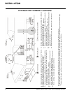
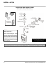
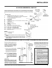
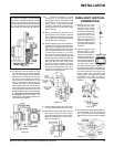
DV STOVE HORIZONTAL VENT KIT (# 946-116 & #946-216) INSTALLATION
Minimum Installation Height:
U39: 59-3/4" ( 1518mm)
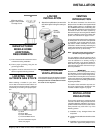
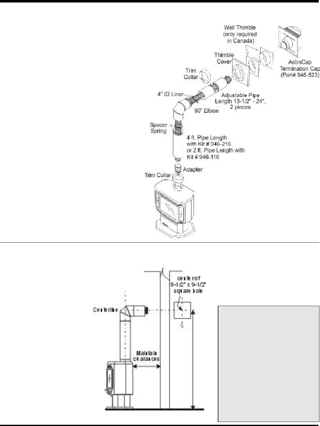
DV STOVE HORIZONTAL VENT KIT
DV Stove Horizontal Vent Kit (2 ft. Part # 946-116 or 4 ft. Part # 946-216) includes all the parts
needed to install the U39 with minimum horizontal and vertical vent dimensions. For installations
that require longer vertical and/or horizontal vents use the Dura-Vent system as shown on page
15.
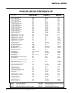
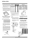
Qty. Description
1) 1 Rigid Pipe Section (Kit # 946-116: 2 ft. (1.2m) length,
Kit # 946-216: 4 ft. (1.2m) length), 6-1/2" (165mm) inside diameter
2) 1 Flex Liner, compressed aluminium 2 ply liner,
4" (102mm) inside diameter
3) 4 spring spacers
4) 1 90 deg. Elbow
5) 1 Adjustable pipe section 13-1/2" to 24" (343mm x 610mm), 2 pieces
6) 1 Thimble Cover
7) 1 Wall Thimble (2 pcs.)
8) 1 Adapter
9) 1 AstroCap Termination Cap
10) 2 Trim Collar
11) 1 tube of Mill-Pac, high temperature sealant
12) 12 Screws, #8 x 1/2" Self tapping, Stainless Steel
13) 13 Screws, #8 x 1/2" Self tapping, Black
14) 4 Screws #8 x 1-1/2" Drill Point, Black
15) 4 Screws #8 x 1-1/2" Drill Point, Stainless Steel
16) 8 Wood screws #8 x 1"
Optional:
946-206 Vinyl Siding Standoff
for AstroCap
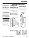
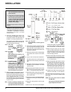
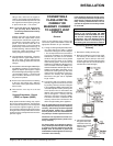
Review the following sequence of in-
structions which are typical of most in-
stallations. The sequence may vary de-
pending on wall thickness. Refer to
vent location and clearance dimen-
sions on pages 8 to 13.
1) Set the unit in its desired location.
Check to determine if wall studs will
be in the way of the venting system,
adjust location until all clearances are
met and there are no obstructions.
Note: A 1-1/2"(38mm) clearance
around the outer pipe must
be maintained except that
only a 1" (25mm) clearance is
needed at the termination
end.
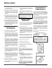
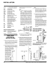
IMPORTANT:
Do not locate termination hood
where excessive snow or ice build-
up may occur. Be sure to check vent
termination area after snow falls,
and clear to prevent accidental
blockage of venting system. When using
snow blowers, make sure snow is not
directed towards vent termination area.
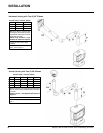
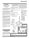
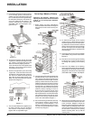
2) Assemble a trial fit to determine the vertical
center-line for the vent termination.
a) Cut a 9-1/2" x 9-1/2" (241mm x 241
mm) square hole on both the interior
and exterior wall.
b) Install wall thimbles on both interior
and exterior wall with 4 wood screws
(#8 x 1") per thimble.
c) Attach the 2 piece adjustable pipe
section to the vent terminal and slide
into position from the exterior. The
larger diameter end of the ad-
justable pipe goes to the vent
terminal.
d) Install the 90
o
elbow onto the adjust-
able pipe to determine the vertical
centerline of the starter collar on the
unit.
Note:
a) Liner sections should be continuous without any joints or
seams.
b) This is an approved system, therefore components in this
system must not be substituted for any other manufac-
turer's products.