


16
Regency U39 ULTIMATE Direct Vent Freestanding Gas Stove
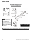
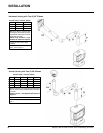
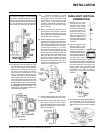
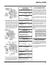
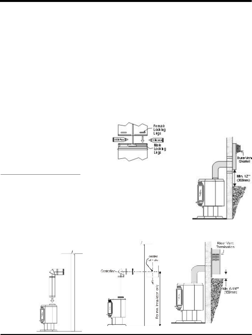
NOTE: For Snorkel terminations in ABOVE
grade installations, follow national or lo-
cal code requirements.
Diagram 3a
Note: Riser
Vent is only for
use in above
grade termi-
nations.
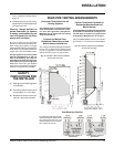
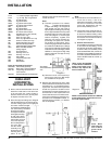
U39: 59-3/4" (1518mm)
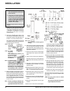
Diagram 2
Note:
a) The horizontal run of vent should have a 1/
4 inch rise for every 1 foot of run
towards the termination. Never allow
the vent to run downward. This could
cause high temperatures and may
present the possibility of a fire.
b) The location of the horizontal vent ter-
mination on an exterior wall must meet
all local and national building codes,
and must not be blocked or obstructed.
For External Vent Terminal Locations,
see diagram on page 8.
c) Snorkel Terminations:
For installations requiring a vertical rise
on the exterior of the building, 14-inch
and 36-inch tall Snorkel Terminations
as shown in Dia. 3 are available, as well
as the standard Riser Vent, see Dia. 3a.
Follow the same installation procedures
as used for standard Horizontal Termi-
nation. NEVER install the snorkel up-
side down.
*Dia 3, 3a & 4: As specified
in CGA B149 Installation
Code. Local codes or reg-
ulations may require dif-
ferent clearances.
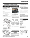
b) Horizontal runs of vent must be sup-
ported every three feet. Wall straps
are available for this purpose.
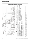
3) With the pipe attached to the stove, slide
the stove into its correct location, and mark
the wall for a 10" x 10" (inside dimensions)
square hole. The center of the square hole
should line up with the centerline of the
horizontal pipe, as shown in diagram 2. Cut
and frame the 10 inch square hole in the
exterior wall where the vent will be termi-
nated. If the wall being penetrated is con-
structed of non-combustible material, i.e.
masonry block or concrete, a 7" diameter
hole is acceptable.
Diagram 3
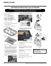
INSTALLATION
DURA-VENT
HORIZONTAL
INSTALLATIONS
1) Set the unit in its desired location. Check to
determine if wall studs or roof rafters are
in the way when the venting system is
attached. If this is the case, you may want
to adjust the location of the unit.
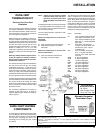
2) Direct Vent pipe and fittings are designed
with special twist-lock connections to con-
nect the venting system to the appliance
flue outlet. A twist-lock appli-
ance adaptor is installed on the
unit at the factory. Assemble
the desired combina-
tion of pipe and elbows
to the appliance adap-
tor with pipe seams
oriented towards the
wall or ceiling, as much
out of view as possi-
ble. The final position-
ing of the pipe
and 90
o
elbow
assembly is de-
termined by the
mounting orien-
tation of the
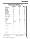
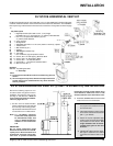
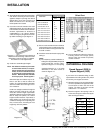
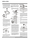
Diagram 1
911B 11"-14 5/8" Adj. Pipe Length-Black
917B 17"- 24" Adj. Pipe Length Black
945 45
O
Elbow Galv.
945B 45
O
Elbow-Black
945G 45
O
Elbow-Swivel Galv.
945BG 45
O
Elbow-Swivel-Black
990 90
O
Elbow Galv.
990B 90
O
Elbow-Black
990G 90
O
Elbow-Swivel Galv.
990BG 90
O
Elbow-Swivel-Black
991 High Wind Term. Cap (Vertical)
980 Vertical Term. Cap
984 Horiz. Sq. Term. Cap
985 Horiz. Sq. High Wind Term. Cap
982 Snorkel-14" Rise Term.Cap
981 Snorkel-36" Rise Term.Cap
940 Wall Thimble-Support/Box
941 Cathedral/Ceiling-Support/Box
3951 Brass Trim-Wall Thimble/
Ceiling Support
963 Firestop Spacer
943 Flashing 0/12-6/12
943S Flashing 7/12-12/12
953 Storm Collar
950 Vinyl Siding Standoff
988 Wall Strap
942 Wall Thimble
Parts not supplied by Dura-Vent
946-506/P Vent Guard (Optional)
640-530 Riser Vent Terminal (Optional)
948-128 Vinyl Siding Shield for Riser
Vent Terminal
946-228 Horizontal Square Termination Cap
adaptor on the stove and twist-locked for
a solid connection.
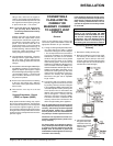
Note:
a) Twist-lock procedure: Four indenta-
tions, located on the female ends
of pipes and fittings, are designed to
slide straight onto the male ends of
adjacent pipes and fittings, by orienting
the four pipe indentations so they match
and slide in to the four entry slots on the
male ends (diagram 1). Push the pipe
sections completely together, then
twist-lock one section clockwise ap-
proximately one-quarter turn, until the
two sections are fully locked. The fe-
male locking lugs will not be visible from
the outside on the Black Pipe or fittings.
They may be located by examining the
inside of the female ends. Apply sealant
"Mill-Pac" to inner pipe and high temp
silicone sealant to outer pipe on every
twist-lock joint.
Hint: Apply
silicone to female
end.