


22 U37-1 Regency
®
ULTIMATE Rear Vent Direct Vent Freestanding Gas Stove
INSTALLATION
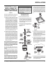
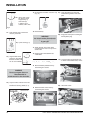
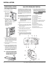
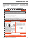
GAS PIPE PRESSURE TESTING
The appliance must be isolated from the gas
supply piping system by closing its individual
manual shut-off valve during any pressure
testing of the gas supply piping system at test
pressures equal to or less than 1/2 psig. (3.45
kPa). Disconnect piping from valve at pressures
over 1/2 psig.
The manifold pressure is controlled by a regu-
lator built into the gas control, and should be
checked at the pressure test point.
Note: To properly check gas pressure, both
inlet and manifold pressures should
be checked using the valve pressure
ports on the valve.
1) Make sure the valve is in the "OFF" posi-
tion.
2) Loosen the "IN" and/or "OUT" pressure
tap(s), turning counterclockwise with a 1/8"
wide fl at screwdriver.
3) Attach manometer to "IN" and/or "OUT"
pressure tap(s) using a 5/16" ID hose.
4) Light the pilot and turn the valve to "ON"
position. Read manometer.
5) The pressure check should be carried out
with the unit burning and the setting should
be within the limits specifi ed on the safety
label.
Diagram 2
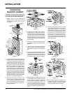
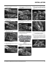
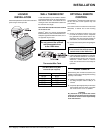
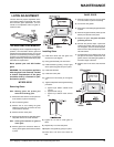
4) The latches should already be at the proper
setting. If they are too hard or too easy
to close, you may want to adjust them by
loosening the locking nut and turning the
latch catch. See diagram 3.
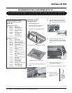
5) Remove the blue plastic protective coating
from the glass.
6) Test the seal around the door by placing
a piece of paper between the unit and
the door, close the door and try to pull
the paper out. If it slips out easily, then
the door is not properly sealed. Tighten or
loosen the latch by turning the latch catch
inward or outward. See diagram 3.
Note: The door latch may require adjust-
ment as the door gasket material
compresses after a few fi res and
after glass replacement. Turn the
latch catch inward or outward.
Diagram 1
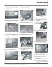
DOOR INSTALLATION
(Packaged Separately)
1) Open the two side panels.
2) Slide the door
onto the two
hinge pins mak-
ing sure the
two pieces are
fl ush together.
See diagram
1.
3) Close the door. The
latch plate must be
centered around the
alignment pin. See
diagram 2. If the latch
plate interferes with the
corner of the stove you
may want to angle the
plate slightly so the door
closes easier.
6) When fi nished reading manometer, turn
off the gas valve, disconnect the hose and
tighten the screw (clockwise) with a 1/8"
fl at screwdriver. Note: Screw should be
snug, but do not over tighten
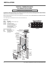
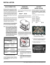
Valve Description
1) Gas on/off knob
2) Manual high/low adjustment
3) Pilot Adjustment
4) Thermocouple Connection
5) Main Operator
6) Outlet Pressure Tap (Manifold Pressure)
7) Inlet Pressure Tap (Supply Pressure)
8) Pilot Outlet
9) Main Gas Outlet
10) Flange Securing Screw Holes
11) Alternative TC Connection Point
12) Thermoelectric Unit
13) Additional Valve Mounting Hole
Diagram 3