


8 U32-4 FPI Direct Vent Gas Insert
VENTING
THE APPLIANCE MUST NOT BE
CONNECTED TO A
CHIMNEY FLUE SERVING A
SEPARATE SOLID FUEL
BURNING APPLIANCE.
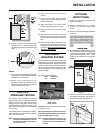
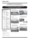
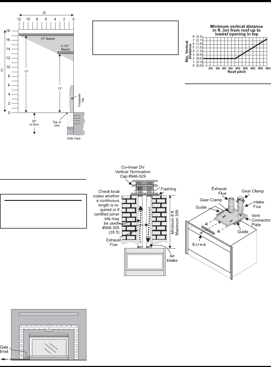
This appliance is designed to be attached to
two 3" (76mm) co-linear aluminium fl ex running
the full length of the chimney. The fl ue length
must be a minimum length of 8 ' (2.44m) and
a maximum of 35' (10.7m). See chart below for
minimum distances from roof. Periodically check
that the vent is unrestricted.
Masonry chimneys may take various contours
which the fl exible liner will accommodate.
However, keep the fl exible liner as straight as
possible, avoid unnecessary bending.
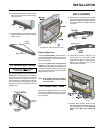
The Air Intake pipe must be attached to the inlet
air collar of the termination cap.
Part # Description
948-305 3" Flex - 35 ft.
946-529 Co-linear DV Vertical
Termination Cap
GAS CONNECTION
GAS CONNECTION WARNING:
Only persons licensed to work
with gas piping may make the
necessary gas connections
to this appliance.
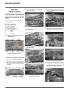
1) If the appliance is to be installed into an
existing chimney system, thoroughly clean
the masonry or factory built fi replace.
2) The appliance is provided with an opening on
the left hand side of the control compartment.
A 3/8" NPT gas supply pipe must be brought
near this inlet hole.
3) Locate the center point where the vent
will pass through the chimney above the
appliance. Move the appliance into the
exact location where it is to be installed.
Ensure that the Insert is level.
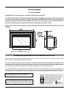
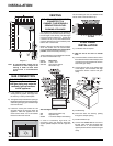
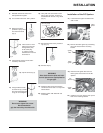
Diagram 3
INSTALLATION
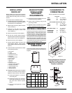
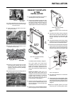
Note: A noncombustible mantel may be
installed at a lower height if the
framing is made of metal studs
covered with a noncombustible
board.
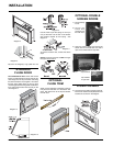
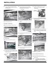
FLUE LINER
INSTALLATION
1) Cut the fl ex liner as required.
2) Mark the end of one liner to indicate
Inlet.
3) Connect the other end of the above liner to
the inlet side of the termination adaptor, seal
connection with high temperature silicone.
Secure with gear clamp.
4) Connect the 2nd liner to the exhaust side
of the adaptor, seal connection with high
temperature silicone. Secure with gear
clamp.
Alternate Approved Caps
980 Vertical Termination Cap
991 High Wind Cap
923GK 3" Co-linear Adaptor with fl ashing
In areas of consistently high winds, we
recommend using the Simpson Dura-Vent
System (923GK adapter and 991 high-wind
cap).
5) Install fl ashing.
6) Insert both liners into chimney, passing
through the damper opening.
7) Install termination cap.
8) Connect the marked end of the liner to
the inlet collar of the vent connector plate
marked with an "I", seal connection with
high temperature silicone. Secure with gear
clamp.
The Air Intake pipe must be attached to the
inlet air collar of the termination cap.