


Regency P48 Zero Clearance Direct Vent Gas Fireplace
22
INSTALLATION
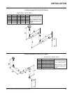
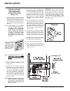
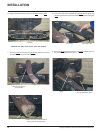
4) Separate the 2 halves of the wall thimble
and securely fasten the one with the tabs
to the outside wall making sure that the tabs
are on top and bottom. Fasten the other
thimble half to the inside wall. The thimble
halves slip inside each other and can be
adjusted for 2 x 4 or 2 x 6 walls. The liners
must slip over the collars a minimum
of 1-3/8".
5) Slip the assembled liner and termination
assembly through the thimble making sure
the termination cap faces up (there are
markings on the cap that show which way
is up). This will position the termination cap
with proper down slope for draining water.
Fasten the cap to the outer wall with the 4
supplied screws.
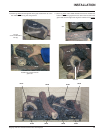
6) Pull the centre 5"(127mm) liner and outer
8"(203mm) liner out enough to slip over the
flue collars of the fireplace. (You may wish
to cut the liner shorter to make it more
workable.) Do not bend liner more than 90
o
.
7) Apply Mill Pac over the fireplace inner collar
and slip the 5"(127mm) liner down over it
and attach with 3 supplied screws.
8) Do the same with the 8"(203mm) liner.
9) Apply a bead of silicone between the thim-
ble and termination and around the outer
edge of the terminal at the wall in order to
keep the water out.
Note: To make the
installation more
aesthetically pleas-
ing, we recom-
mend framing out a
square to mount
the terminal to.
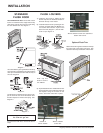
INSTALLATION
PROCEDURES
for Regency Direct Vent
System (Flex)
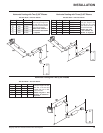
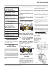
1) Locate the unit in the framing, rough in the
gas (preferably on the right side of the unit)
and the electrical (Junction block is on the
left side) on the left. Locate the centerline
of the termination and mark wall according-
ly. Cut a 11"(279mm) hole in the wall (inside
dimension).
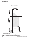
Note: A top clearance of 2-1/2"(64mm)
and side & bottom clearance of
1-1/2"(38mm) must be maintained
except that only a 1" (25mm) clear-
ance is needed at the termination
end. We recommend framing a
11"(279mm) x 11"(279mm) (inside
dimensions) hole to give struc-
tural rigidity for mounting the ter-
mination.
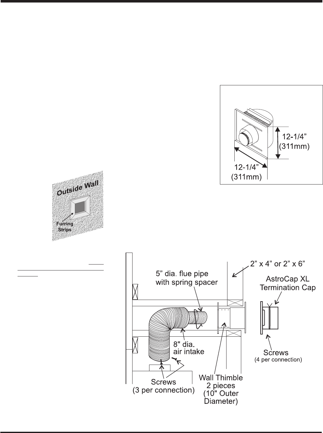
Note: If installing termination on a siding
covered wall, furring strips must
be used to ensure that the termi-
nation is not recessed into the
siding.
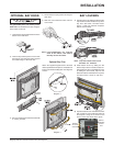
2) Level the fireplace and fasten it to the
framing using nails or screws through the
nailing strips.
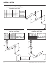
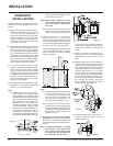
3) Assemble the vent assembly by applying
Mill Pac to the 5"(127mm) inner collar of the
termination and slipping the 5"(127mm) liner
over it at least 1-3/8" (35mm). Fasten with
the 3 screws (drilling pilot holes will make
this easier). Apply Mill Pac or high temper-
ature silicone to the 8"(203mm) flex pipe and
slip it over the 8" outer collar of the vent
terminal at least 1-3/8"(35mm) and fasten
with the 3 screws.
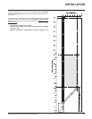
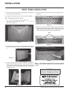
NOTE: Horizontal sections must be sup-
ported at intervals not exceeding 3
feet (0.9 meter). (Flame picture and
performance will be affected by
sags in the liner).
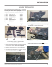
IMPORTANT: Do not locate termination
hood where excessive snow or ice build-
up may occur. Be sure to check vent
termination area after snow falls, and clear
to prevent accidental blockage of venting
system. When using snow blowers, make
sure snow is not directed towards vent
termination area.
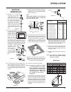
ASTROCAP XL
DIMENSIONS