


Regency
®
P48-2 Zero Clearance Direct Vent Gas Fireplace 11
VENTING
INTRODUCTION
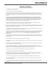
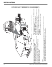
The P48-2 uses the "balanced fl ue" technology
Co Axial system. The inner liner vents products
of combustion to the outside while the outer
liner draws outside combustion air into the
combustion chamber thereby eliminating the
need to use heated room air for combustion and
losing warm room air up the chimney.
Note: These flue pipes must not be
connected to any other appliance.
The gas appliance and vent system must be
vented directly to the outside of the building,
and never be attached to a chimney serving a
separate solid fuel or gas burning appliance.
Each direct vent gas appliance must use it's own
separate vent system. Common vent systems
are prohibited.
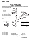
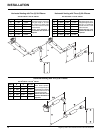
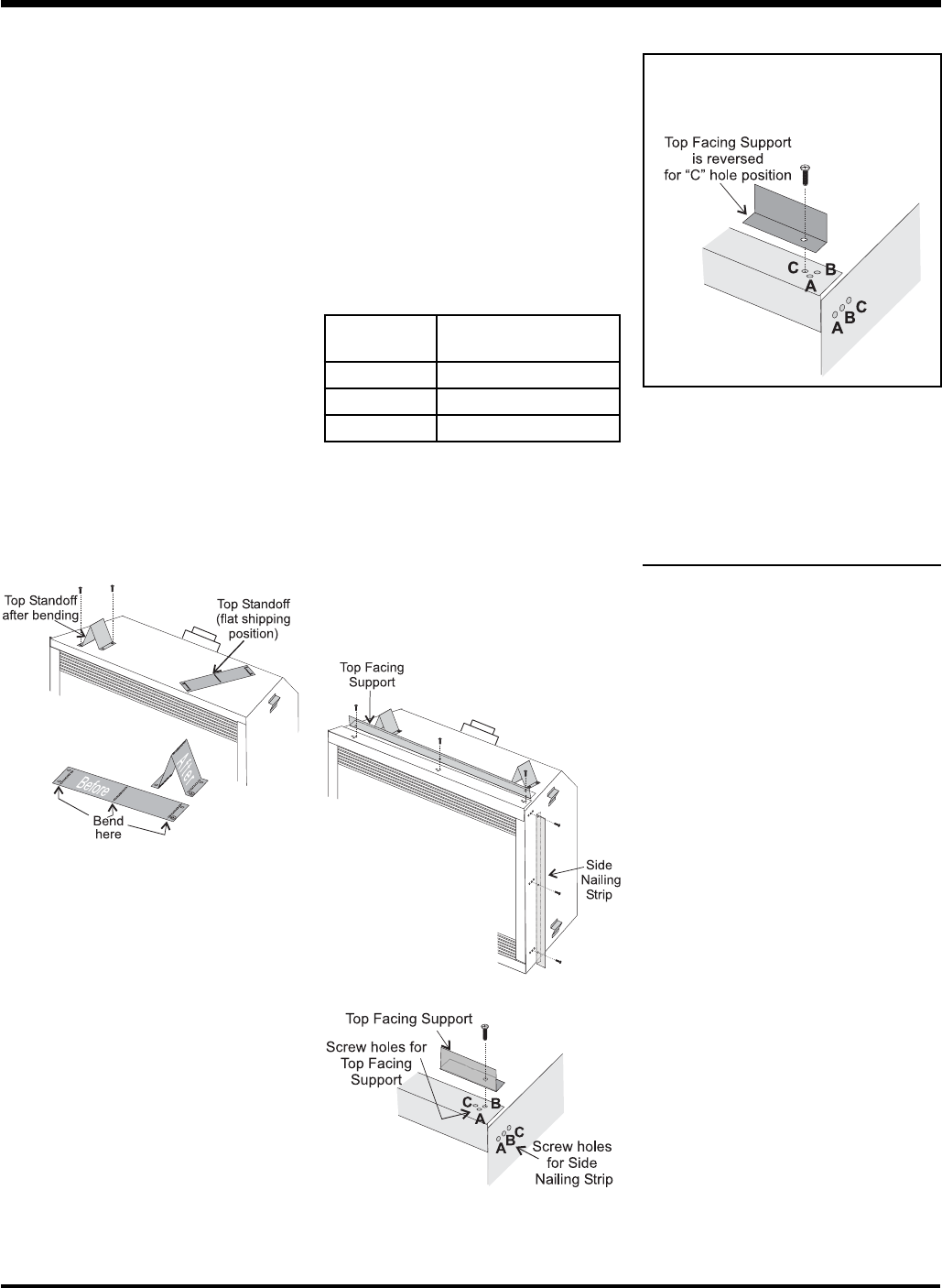
* For "C" screw position the top facing support
is reversed.
"C" Screw Position:
For a facing material depth of 1-1/4" (32mm),
the top facing support must be reversed.
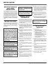
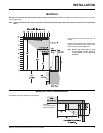
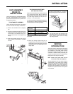
UNIT ASSEMBLY
PRIOR TO
INSTALLATION
The Top Facing Support, the Side Nailing Strips
and the 2 Top Standoffs must be correctly
positioned and attached to the top before unit
is slipped into position.
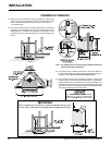
TOP STANDOFF ASSEMBLY
The top standoffs are shipped in a fl at position
and must be folded into shape and attached.
1) Remove the standoffs from the fi replace
top.
2) Take each standoff and bend into the correct
shape. Bend up at the bend lines until the
screw holes in the standoff and the pre-
punched screw holes on the fi replace top
line up.
3) Attach the standoff securely to the top
with 2 screws per standoff (on opposite
corners).
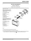
TOP FACING SUPPORT AND
SIDE NAILING STRIPS
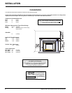
Determine the total thickness of facing material
(e.g. drywall plus ceramic tiles) to allow the
fi nished surface to be fl ush with the front of the
unit. Total facing thickness can vary from 1/2"
(13mm) to 1-1/4" (32mm) thick.
The Top Facing Support & Side Nailing Strips can
be mounted in 3 different positions depending
on the thickness of the facing material.
1) Mount Top Facing Support using the 3
supplied screws into the three pre-punched
screw holes on the top front of the unit. Use
hole positions A, B, or C depending on your
facing depth.
2) Use the same screw hole position for the
Side Nailing Strips as was used for the Top
Facing Support. Attach each side nailing
strip using 3 screws.
INSTALLATION
Screw
Position
Facing Material Depth
A 1/2" / 13mm
B 7/8" / 22mm
C* 1-1/4" / 32mm