


Regency P48-1 Zero Clearance Direct Vent Gas Fireplace
32
INSTALLATION
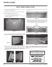
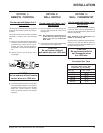
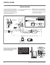
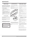
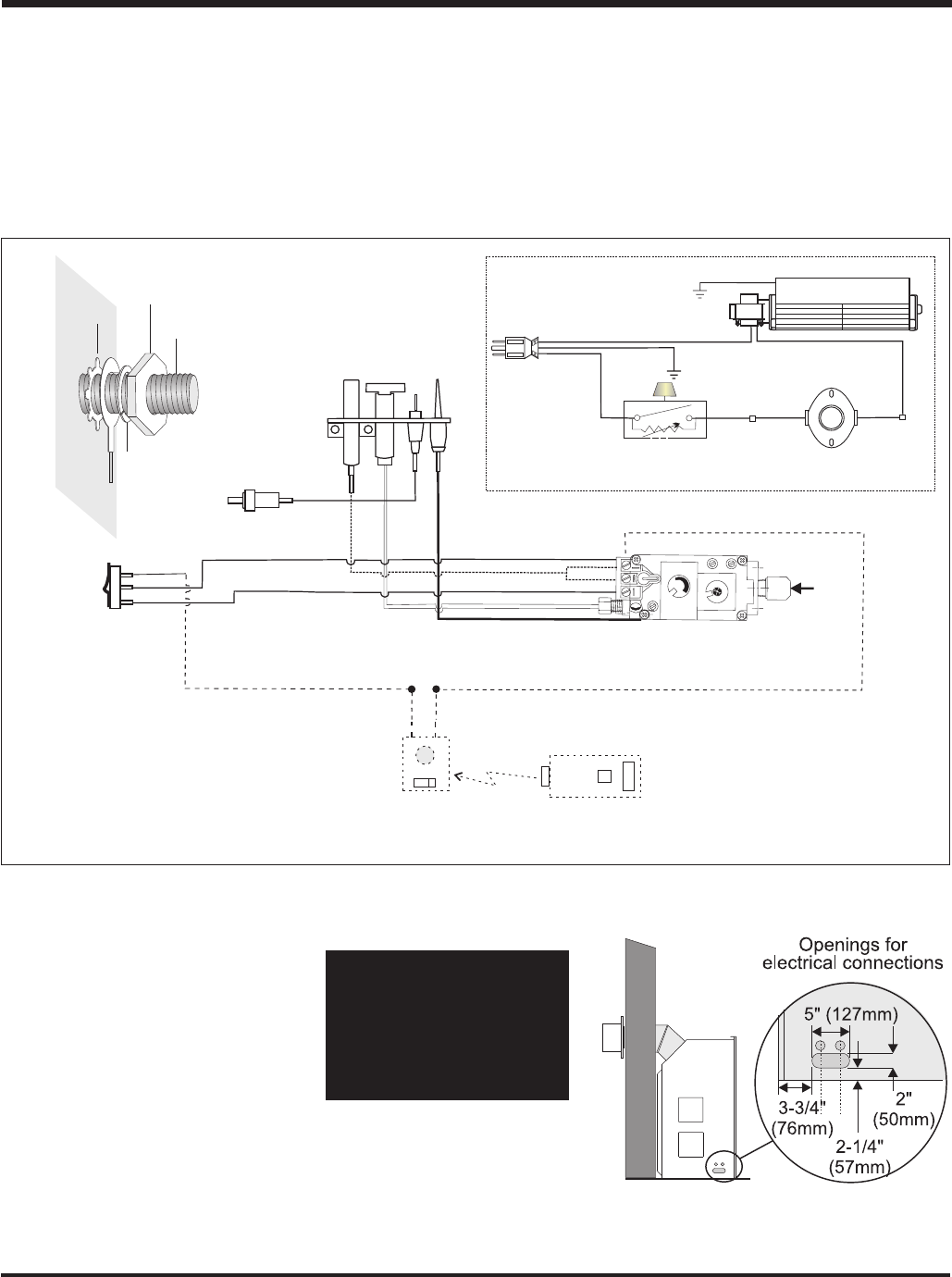
WIRING DIAGRAM
CAUTION: Label all wires
prior to disconnection
when servicing controls.
Wiring errors can cause
improper and dangerous
operation.
No electrical power supply is required for the
gas control to operate. 120 Volt AC power is
needed for the fan switch and blower. The fan
can be hard wired if desired. A terminal block
is provided on the left hand side of the unit. A
three wire power cord can also be used and
plugged into a suitable receptacle.
(Do not cut the ground terminal off under
any circumstances.)
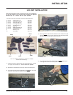
NOTE: Even if the fan is not purchased with the
unit, it is still a good idea to hardwire the terminal
block in case the fan is installed at a later date.
** However DO NOT leave this connection
live until the fan is installed.**
Caution: Ensure that the wires do
not touch any hot surfaces and are
away from sharp edges.
Ground
Green
Neutral
Live
Black Red Red
Fan Thermodisc
(normally open)
Ground
ON OFF
Rotary Speed
Control
120V AC
60 Hz
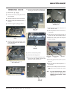
Fan
Lockwasher
Fan
ground wire
Nut
#8 Ground Lug
(for mobile home)
Star washer
Piezo
Ignitor
To Thermocouple IN
Pilot
Assembly
H
I
L
O
O
F
F
O
N
P
I
L
O
T
Gas Pilot
Thermopile
Thermocouple
Electrode
Remote Transmitter
(Optional)
ON OFF
Regency
Remote Receiver
or Thermostat
(Millivolt) (Optional)
Brown
Red
T-Stat
Black
White
"S.I.T" Valve
Burner
ON
OFF
Thermostat
(To THTP)
(To TH)
White
Gas
In