


Regency P33-3 Zero Clearance Direct Vent Gas Fireplace
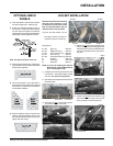
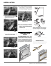
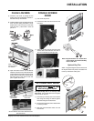
INSTALLATION
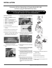
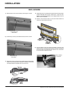
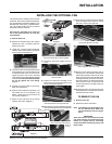
Caution: Ensure that the wires do
not touch any hot surfaces and are
away from sharp edges.
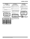
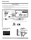
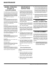
WIRING DIAGRAM
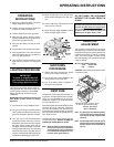
This heater does not require a 120V A.C. supply for operation. In case of a power failure, the burner switch and the optional remote control/thermostat
will continue to operate. However, a 120V A.C. power supply is needed for the fan/blower operation.
(Do not cut the ground terminal off under any circumstances.)
NOTE: Even if the fan is not purchased with the unit, it is still a good idea to bring power to the receptacle box (provided with the unit)
in case the fan is installed at a later date.
CAUTION: Label all wires
prior to disconnection
when servicing controls.
Wiring errors can cause
improper and dangerous
operation.
Ground
Green
Neutral
Live
Black Red Red
Minimum Convection
Air Temp. Switch
Ground
ON OFF
Rotary Speed
Control
120V AC
60 Hz
Fan
Piezo
Ignitor
To Thermocouple IN
Pilot
Assembly
H
I
L
O
O
F
F
O
N
P
I
L
O
T
Gas Pilot
Thermopile
Thermocouple
Electrode
Lockwasher
Fan
ground wire
Nut
#8 Ground Lug
(mobile home
approved)
Star washer
Remote Transmitter
(Optional)
ON OFF
Regency
Remote Receiver
or Thermostat
(Millivolt) (Optional)
Brown
Red
T-Stat
Black
White
"S.I.T" Valve
Burner
ON
OFF
Thermostat
(To THTP)
(To TH)
White
Gas
In