


6 F37 Regency
®
Rear Flued Room Sealed Freestanding Gas Heater
Make it a practice to have all of your gas
appliances checked annually.
13) Do not slam shut or strike the glass door.
14) Under no circumstances should any solid
fuels (wood, paper, cardboard, coal, etc.)
be used in this appliance.
15) The appliance area must be kept clear and
free of combustible materials, (gases and
other fl ammable vapours and liquids).
INSTALLATION
CHECKLIST
1) Locate your gas stove. Refer to the following
sections where applicable:
a. Clearances to Combustibles
b. Exterior Flue Termination Locations
c. Planning Your Flue Installation
d. Flueing
e. Flueing Installation Precaution
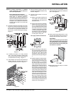
2) Install fl ueing. Check all fl uing requirements.
See "Flueing" to "Vertical Termination with
Co-Linear Flex System" sections.
3) Make gas connections. Refer to the "Gas
Connection" section.
Test the pilot. Must be as per diagram in the
"Maintenance Instruction" section.
4) If necessary, convert from NG to LPG.
Refer to "Conversion Kit from NG to LPG"
section.
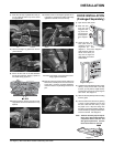
5) Install standard and optional features. Refer
to the following sections where applicable.
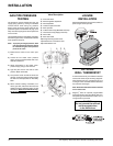
a. Log Set Installation
b. Door Installation
c. Louvre Installation
d. Optional Wall Thermostat
e. Optional Remote Control
6) Test Gas Pressure. Refer to the "Gas Pipe
Pressure Testing" section.
7) Final check. Refer to the "Final Check" sec-
tion.
Before leaving this unit with the customer, the
installer must ensure that the appliance is fi r-
ing correctly and operation fully explained
to customer.
This includes:
1) Clocking the appliance to ensure the correct
fi ring rate (rate noted on label) after burning
appliance for 15 minutes.
2) If required, adjusting the primary air to ensure
that the fl ame does not carbon. First allow
the unit to burn for 15-20 min. to stabilize.
CAUTION: Any alteration to the product that
causes sooting or carboning that results
in damage is not the responsibility of the
manufacturer.
LOCATING YOUR
REGENCY GAS STOVE
When selecting a location for your stove, ensure
that the clearances listed above are met as well
as ensuring that there is adequate accessibility
for servicing and proper operation.
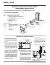
See the "Exterior Flue Termination Locations"
section for Flue Termination requirements.
This appliance is Listed for bedroom installations
when used with a Listed Millivolt Thermostat.
Some areas may have further requirements,
check local codes before installation.
This appliance is Listed for Alcove installations,
maintain minimum Alcove clearances as follows,
minimum ceiling height of 1.7m, minimum width
of 1.0m and a maximum depth of 0.9m.
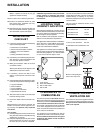
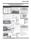
INSTALLATION
This unit can be installed on a solid combustible
surface like a wood fl oor. This unit can also be
installed directly on carpeting or vinyl when
the bottom pedestal cover plate (provided with
unit) is installed.
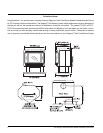
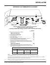
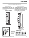
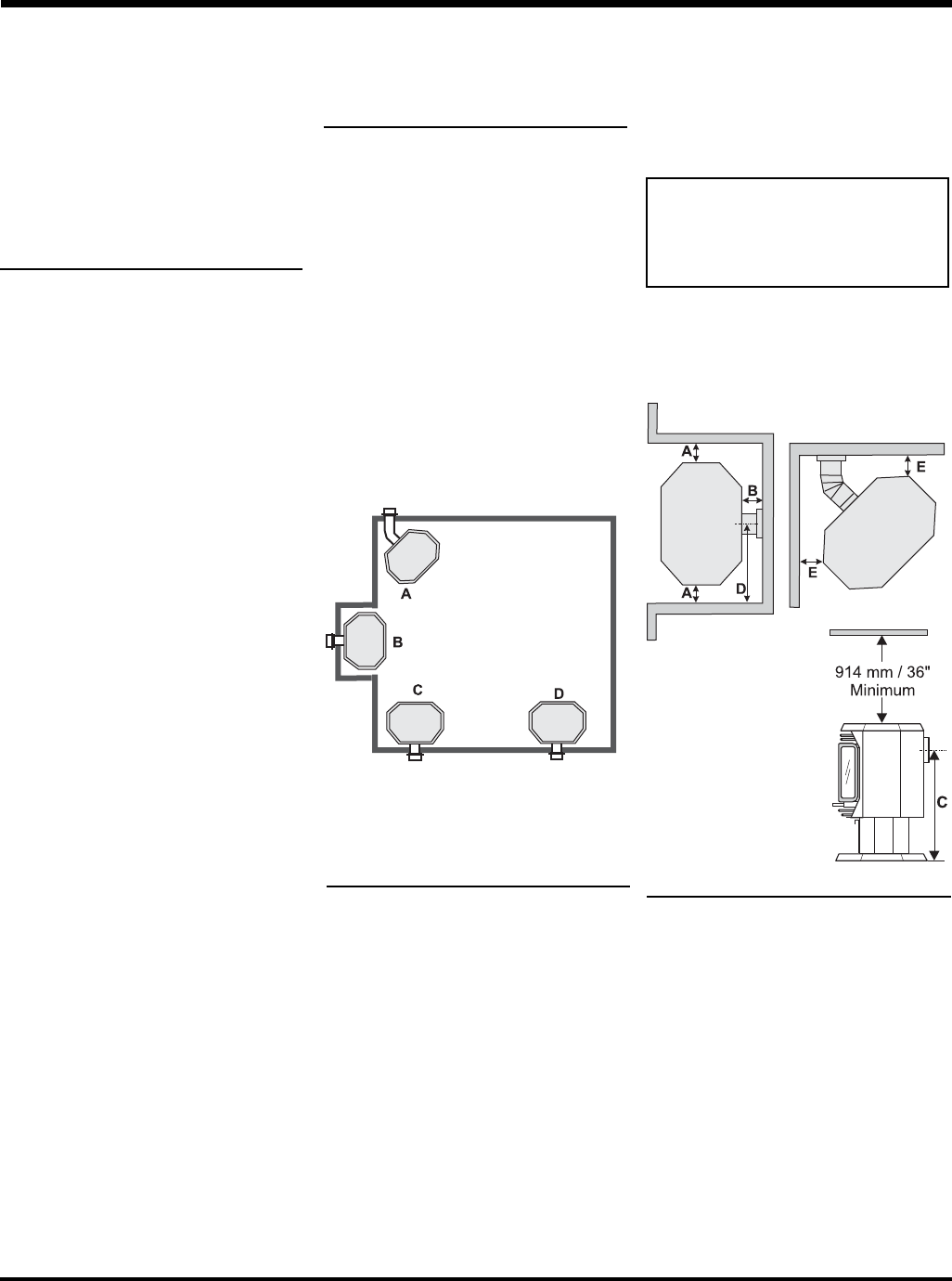
Use the minimum clearances shown in the
diagrams below:
F37-NG & F37-LPG Clearances
A Side Wall to Unit 190 mm
B Back Wall to Unit 76 mm
E Side Wall to Unit 114 mm
F37-NG & F37-LPG
Reference Dimensions
C Floor to Flue Centerline 635 mm
D Side Wall to Flue Centerline 521 mm
A) Cross Corner
B) Flush with Wall/Alcove
C) Flat on Wall Corner
D) Flat on Wall
CLEARANCES TO
COMBUSTIBLES
The clearances listed are MINIMUM distances.
Measure the clearance to both the appliance and
the chimney connector. The farthest distance is
correct if the two clearances do not coincide.
For example, if the appliance is set as indicated
in one of the diagrams but the connector is too
close, move the stove until the correct clearance
to the connector is obtained.
This appliance may be installed only with the
clearances as shown in the situations pictured.
Do not combine clearances from one type of
installation with another in order to achieve
closer clearances.
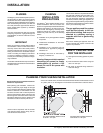
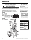
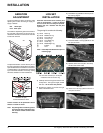
COMBUSTION AND
VENTILATION AIR
The combustion air from this appliance is drawn
from outside the building through the outer fl ue.
Extra provision for combustion air inside the
room is not required.
Minimum ceiling height is
914mm from top of unit.