


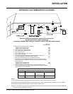
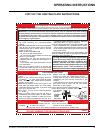
F37 Regency
®
Rear Flued Room Sealed Freestanding Gas Heater 15
Diagram 2
Diagram 3
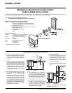
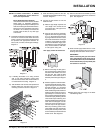
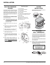
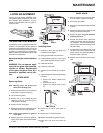
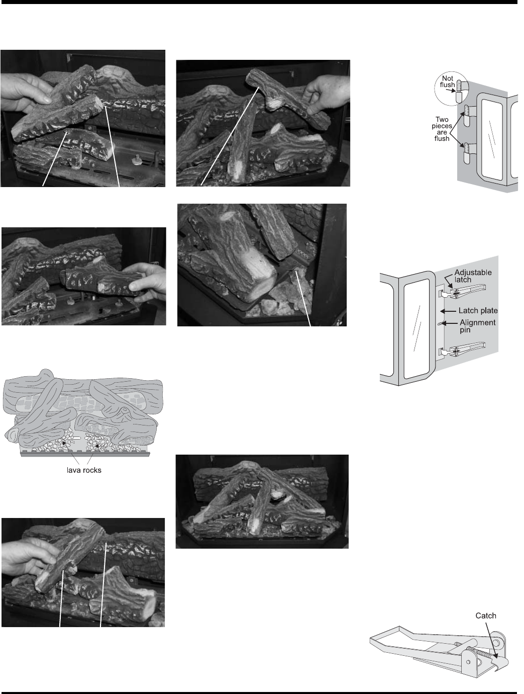
4) The latches should already be at the proper
setting. If they are too hard or too easy
to close, you may want to adjust them by
loosening the locking nut and turning the
latch catch. See diagram 3.
5) Remove the blue plastic protective coating
from the glass.
6) Test the seal around the door by placing
a piece of paper between the unit and
the door, close the door and try to pull
the paper out. If it slips out easily, then
the door is not properly sealed. Tighten or
loosen the latch by turning the latch catch
inward or outward. See diagram 3.
Note: The door latch may require adjust-
ment as the door gasket material
compresses after a few fi res and
after glass replacement. Turn the
latch catch inward or outward.
Diagram 1
DOOR INSTALLATION
(Packaged Separately)
1) Open the two side panels.
2) Slide the door
onto the two
hinge pins mak-
ing sure the
two pieces are
fl ush together.
See diagram
1.
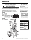
Cutout
Pin
Notch
D)02-46
B)02-56
A)02-65
E)02-45
Bracket
A)02-65
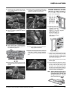
The bottom right edge of Log G)02-48 must sit
snugly against the bracket
Side View
G)02-48
E)02-45
F)02-47
3) Close the door. The
latch plate must be
centered around the
alignment pin. See
diagram 2. If the latch
plate interferes with the
corner of the stove you
may want to angle the
plate slightly so the door
closes easier.
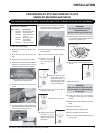
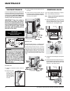
7) Place the Left Top Log D)02-46 on the pin
on Log B)02-56 and on top of the cutout
on Log A)02-65.
E)02-45
C)02-44
8) Place Front Right Log E)02-45 on the two
pins as shown.
9) Place the lava rock in the area between
the left and right logs, leaving a space in
the middle for log (F) 02-47.
CutoutNotch
F)02-47
E)02-45
10) Place the notch in Center Log F)02-47 over
Log E)02-45 and across the cutout on Log
A)02-65.
11) Position notch in Front Right Log G)02-48 on
Log F)02-47 and push the bottom right edge
against the bracket on the burner tray.
G)02-48
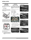
12) Test fi re to ensure proper light off (make sure
fl ame fl ows smoothly from one end of burner
to the other. If there is any fl ame hesitation,
check that area for any blockage of the burner
port.
F)02-47
E)02-45
A)02-65
G)02-48
D)02-46
B)02-56
C)02-44
INSTALLATION