


Regency Freestanding Woodstove
11
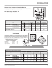
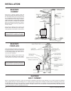
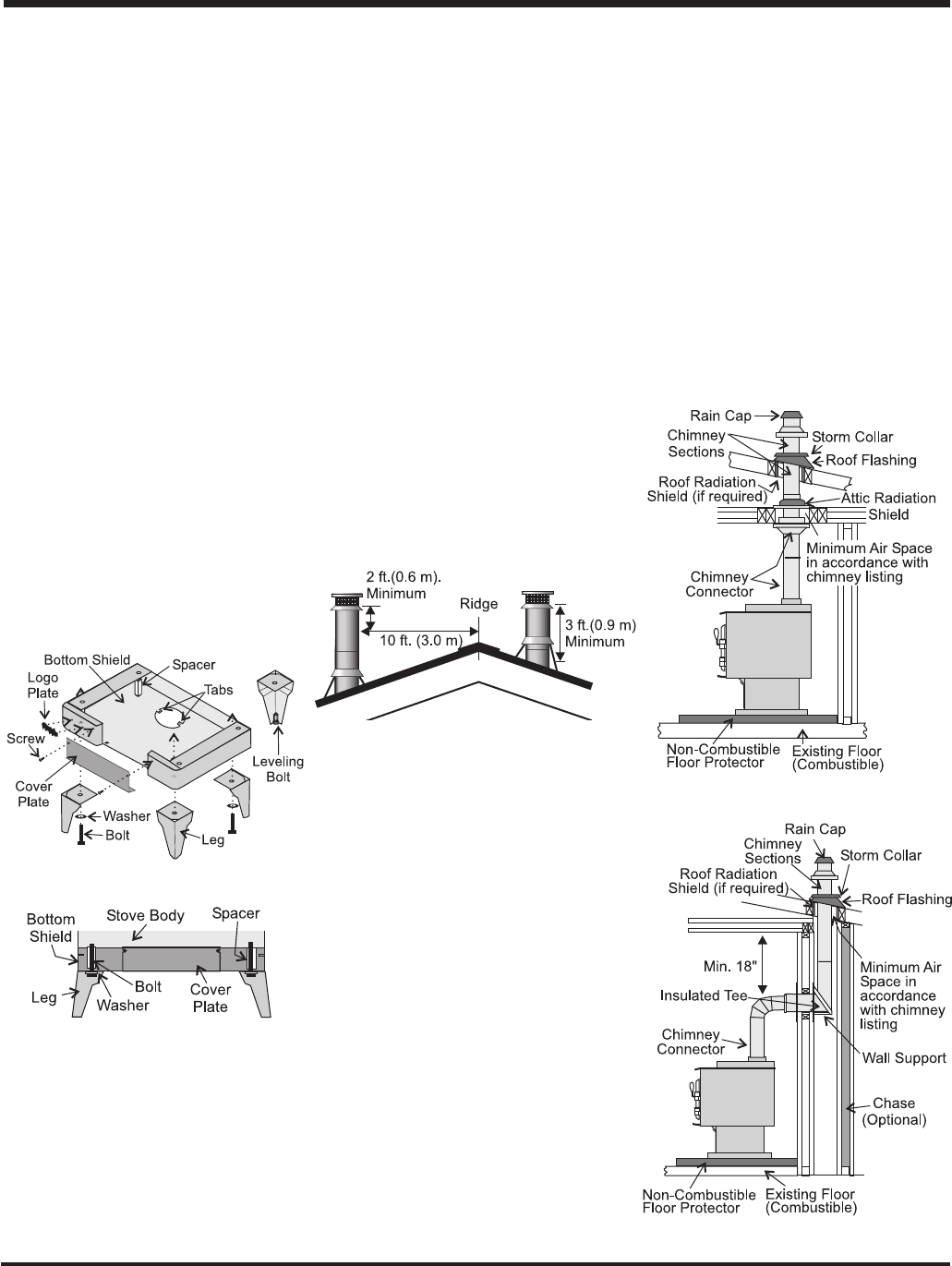
Horizontal Installation
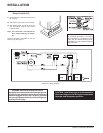
Standard Ceiling Installation
8) To complete your chimney installation, in-
stall the double wall connector pipe from
the stove’s flue collar to the chimney sup-
port device.
9) If you are using a horizontal connector, the
chimney connector should be as high as
possible while still maintaining the 18" min-
imum distance from the horizontal connec-
tor to the ceiling.
10) NOTE: Residential Close Clearance
and Alcove installations require a list-
ed double wall connector from the
stove collar to the ceiling level.
The diagrams below illustrate one way to install
your unit into a standard ceiling or with a
horizontal connector. Check with your dealer
or installer for information on other options
available to you.
INSTALLATION
STEP BY STEP
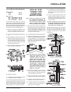
CHIMNEY AND
CONNECTOR
INSTALLATION:
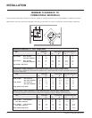
Note: These are a generic set of chim-
ney installation instructions. Al-
ways follow the manufacturers
own instructions explicitly. Check
Table 1 on page 14 for the Mini-
mum Recommended Flue Heights.
1) With your location already established, cut
and frame the roof hole. It is recommended
that no ceiling support member be cut for
chimney and support box installation. If it is
necessary to cut them, the members must
be made structurally sound.
2) Install radiant shield and support from above.
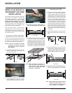
3) Stack the insulated pipe onto your finish
support to a minimum height of 3 feet above
the roof penetration, or 2 feet above any
point within 10 feet measured horizontally.
There must be at least 3 feet of chimney
above the roof level.
Note: Increasing the chimney height
above this minimum level will
sometimes help your unit to
“breathe” better by allowing a
greater draft to be created. This
greater draft can decrease prob-
lems such as, difficult start-ups,
back-smoking when door is open,
and dirty glass. It might be suffi-
cient to initially try with the mini-
mum required height, and then if
problems do arise add additional
height at a later date.
4) Slide the roof flashing over your chimney
and seal the flashing to the roof with
roofing compound. Secure the flashing to
your roof with nails or screws.
5) Place the storm collar over the flashing,
sealing the joints with a silicone caulking.
6) Fasten the raincap with spark screens (if
required) to the top of your chimney.
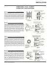
7) For optimum efficiency when installing into
a masonry chimney, size accordingly, i.e.
the 6" flue dia. is 28.28 sq.in.
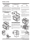
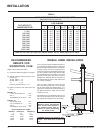
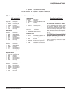
Leg and Bottom Shield Assembly
Bottom Shield
Small 850-121
Large 850-321
Legs (set of 4)
Steel - Painted Black 850-125
Cast - Painted Black 850-126
Cast - Gold Plated 850-127
The instructions below apply to the steel leg,
painted cast leg and the gold plated cast leg. It
will be easier to attach the legs to the stove if
the stove is tipped on its back (preferably on a
soft surface to prevent scratching). Ensure to
be extremely careful when tipping stove.
1) Remove the 4 bolts from underside of the
base of the pedestal and discard. Also
remove cover plate and put to the side.
2) Line up the heat shield with the bottom of the
unit.
3) Start threading the bolt and washer (sup-
plied with the bottom shield) for about 1/4
of the way through the leg with the wash-
ers being underneath the legs. Ensure that
the legs are properly aligned with heat
shield and tighten the bolts.
4) Level the stove by adjusting the levelling
bolts in the bottom of each leg.
5) Reinstall cover plate.
6) Install logo plate onto heat shield by placing
in 2 holes as shown in diagram.
If you are installing outside combustion air, bend
the tabs out 90 degrees. Pipe fresh air into the
bottom shield by using a minimum 4" duct pipe
with a mesh grill at the outside termination.
Attach the pipe to the 2 tabs with screws.