


7
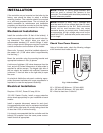
Power to the Controller
• Observe (follow proper) polarity.
•
Observe proper wire colors while making electrical
connections.
• Provide an external surge suppressor capable of
maintaining system integrity.
• Provide overload protection and a disconnect
means for equipment serviceability as required by
local and state code.
• Conduit cannot be used as the ground. (There
must
be a “WIRED” ground.)
• Very Important: A grounding electrode con-
ductor shall be used to connect the equipment
grounding conductors, the equipment enclosures,
and where the system is grounded, the grounded
service conductor to the grounding electrode.
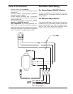
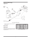
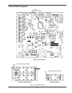
Fig. 2: Wiring Diagram
Controller Field Wiring
For Single-Stage (ON/OFF) Boilers
A
ll stage connections on the control board are con-
nected at the {TH} (Thermostat) location on the boiler
wiring diagram.
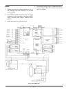
For Multiple-Stage Boilers
First stage connections on the control board are con-
nected at the {TH} (Thermostat) location on the boiler
wiring diagram. Second (or third, etc.) stage connec-
tions on the control board are connected at the
locations shown on the boiler wiring diagram.