


3
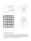
3. INSTALLATION REQUIREMENTS
The equipment must be installed in accordance with local codes, or in the absence of local codes with the
latest edition of the National Fuel Gas Code, ANSI Z223.1, the National Electrical Code, ANSI/NFPA 70.
The equipment shall be installed in accordance with those installation regulations in force in the local area where
the installation is to be made. These shall be carefully followed in all cases. Authorities having jurisdiction shall
be consulted before installations are made.
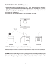
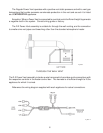
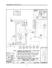
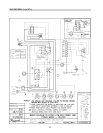
MOUNTING POWER VENT ASSEMBLY
Follow these instructions if the PowerVent venting system was purchased as an option
assembly kit.
1. Remove existing pagoda top (outdoor units) or drafthood (indoor units). To remove the
pagoda top, push the four brackets inward and pull up the pagoda top. The pagoda may
then be discarded.
2. Unscrew the four screws holding the outer top using a phillips screw driver. Remove the
jacket top.
3. Replace the inner stack adapter. If the heater had a drafthood installed previously, re-
move the inner stack adapter and replace it with the PowerVent stack adapter. Otherwise,
install the PowerVent stack adapter.
4. Unscrew the access panel on the right side of the appliance. Set aside the screws with
the access panel.
5. Remove the knurled screw holding the front door and set it aside with the door.
6. Mount the jacket top above the unit. Note: Do not install at this point.
7. Mount the Power Vent on the outer top.
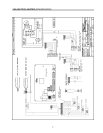
8. Route the conduit harness of the PowerVent thru the outer top hole, around the adapter
towards the back of the unit. Continue routing the harness thru the corner slot, which
leads to open area behind the access panel. Finally, route only the wire harness thru the
7/8” grommet hole located on the sway brace. Follow instructions on page 7 to wire the
PowerVent. Note: Newer units have a 7/8” grommet located on the rain shield, which
would eliminate routing the harness around the back corner.
9. Re-mount the jacket top to its original position and screw in the four screws holding it
down to the appliance.
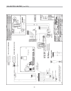
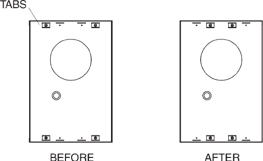
10.If the appliance is a 181, 182, 330 or 331, remove the tabs underneath the power vent
using a 5/16” nut driver and relocate the closer to the center of the Power Vent.
Fig #9372