19
Install a separate disconnect means for each load.
Use appropriate-sized wire as defined by NEC, CSA
and/or local code. All primary wiring should be 125% of
minimum rating.
It is strongly recommended that all individually-pow-
ered control modules and the heater should be
supplied from the same power source.
Surge Protection
Microprocessor-based and solid state controls are vul-
nerable to damage from voltage and amperage
fluctuations in the power supply. All sensitive control
components should be protected by a suitable com-
mercial-grade surge protection device.
If any of the original wire as supplied with the heater
must be replaced, it must be replaced with 105°C wire
or its equivalent.
Check the Power Source
Making the Electrical Connections
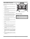
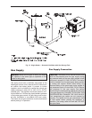
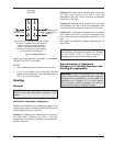
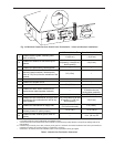
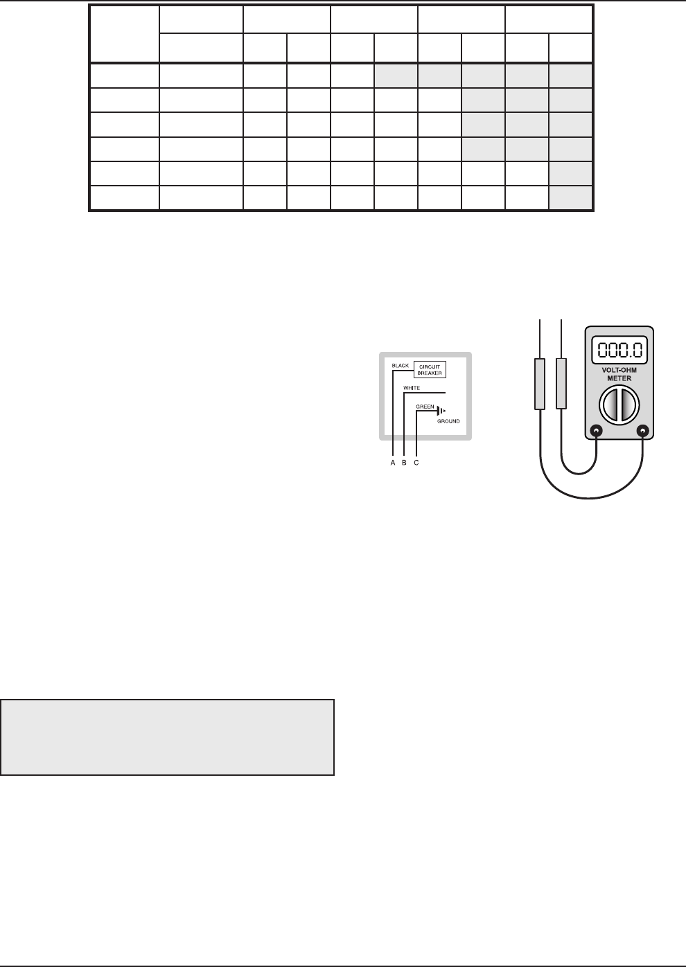
Refer to Fig. 14 and the Wiring Diagram.
1. Verify circuit breaker is properly sized by referring
to heater rating plate. A dedicated circuit breaker
should be provided.
2. Turn off all power to the heater. Verify that power
has been turned off by testing with a volt-ohm
meter prior to working with any electrical connec-
tions or components.
3. Observe proper wire colors while making electrical
connections. Many electronic controls are polarity
sensitive. Components damaged by improper
electrical installation are not covered by warranty.
4. Provide an external surge suppressor capable of
maintaining system integrity.
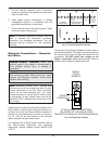
Fig. 14: Check Power Source
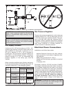
WARNING: Using a volt-ohm meter (VOM), check
the following voltages at the terminal block inside the
unit. Make sure proper polarity is followed and house
ground is proven.
Model
No.
I
nput
3
/4”
1
”
1
-1/4”
1
-1/2”
(KBTUH) N P N P N P N P
HD101 100 105 385 340
HD151 150 50 180 160 530 600
HD201 199 30 95 95 355 360
HD251 250 20 50 60 230 240
HD301 299 15 35 45 170 170 550 360
HD401 399 5 20 25 80 100 365 210
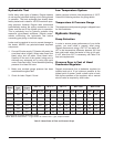
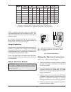
Table H: Maximum Equivalent Pipe Length
Natural gas – 1,000 BTUH per ft
3
, .60 specific gravity at 0.5 in. WC pressure drop
Propane gas – 2,500 BTUH per ft
3
, 1.50 specific gravity at 0.5 in. WC pressure drop
AC = 108 Volts AC Minimum, 132 Volts AC MAX
AB = 108 Volts AC Minimum, 132 Volts AC MAX
BC = < 1 Volt AC


