


18
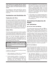
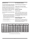
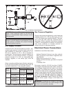
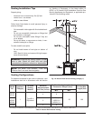
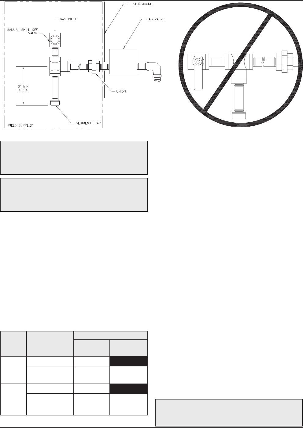
Fig. 13: Sediment Trap Orientation
Gas Supply Pressure
A minimum of 4 in. WC and a maximum of 10.5 in. WC
upstream gas pressure is required under load and no
load conditions for natural gas. A minimum of 11 in.
WC and a maximum of 13 in. WC is required for
propane gas. The gas pressure regulator supplied on
the heater is for low pressure service. If upstream
pressure exceeds 14 in. WC, an intermediate gas
pressure regulator, of the lockup type, must be
installed.
When connecting additional gas utilization equipment
to the gas piping system, the existing piping must be
checked to determine if it has adequate capacity.
CAUTION: Do not use Teflon tape on gas line pipe
thread. A pipe compound rated for use with gas
systems is recommended. Apply sparingly only on
male pipe ends.
CAUTION: Support gas supply piping with
hangers, not by the heater or its accessories. Ensure
the gas piping is protected from physical damage
and freezing where required.
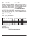
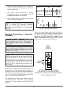
Gas Pressure Regulator
The gas valve pressure regulator(s) on the heater are
nominally preset at 3 in. WC for natural gas, and 10.0
in. WC for propane gas manifold pressure. The pres-
sure at the gas valve outlet tap, measured with a
manometer, while in operation should be as indicated
in Table G. If an adjustment is needed, turn the adjust-
ment screw clockwise to increase pressure or
counter-clockwise to decrease pressure.
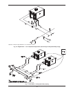
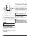
Electrical Power Connections
Installations must follow these codes:
· National Electrical Code and any other national,
state, provincial or local codes or regulations hav-
ing jurisdiction
· Safety wiring must be N.E.C. Class 1
· Heater must be electrically grounded as required
by N.E.C.
· In Canada, C22.1
The heater is wired for 120 VAC, less than 12 AMPS.
The voltage is indicated on the tie-in leads. Consult the
wiring diagram shipped with the heater in the instruc-
tion packet. The remote tank control stat, thermostat,
or electronic heater control as applicable, may be con-
nected to stage selector terminal (See wiring diagram).
24 Volts are supplied to this connection through the
heater transformer. DO NOT attach line voltage to
the stage connections. Before starting the heater
check to ensure proper voltage to the heater and
pump.
Firing
Stage
Gas Valve
Gas Type
Natural
+/- 0.1"WC
LP/Propane
+/- 0.1"WC
Hi-Fire
Invensys 3.3" WC
Honeywell or
White-Rodgers
3.1" WC 9.6" WC
Lo-Fire
Invensys 1.2" WC
Honeywell or
White-Rodgers
1.4" WC 3.6" WC
Table G: Pressure at Gas Valve Outlet Tap
WARNING: Connecting line voltage to the stage
connection terminal block will cause damage to the
unit that is not covered by warranty.