CONNECTIONS - ELECTRICAL
23
WIRING A POWER FLUED SYSTEM TO THE WATER HEATER
An indoor model can be wired to a power flued system. A power flued system
must be designed by a qualified person to suit the particular installation. The
power flue system must be interlocked with the water heater(s) to prevent the
water heater(s) from operating if the power flue is not working.
Where multiple water heaters are connected to a power flue, the control system
must be designed so that any of the water heaters can activate the fan in the
flue and none of the burners can come on until the flow in the flue has been
established.
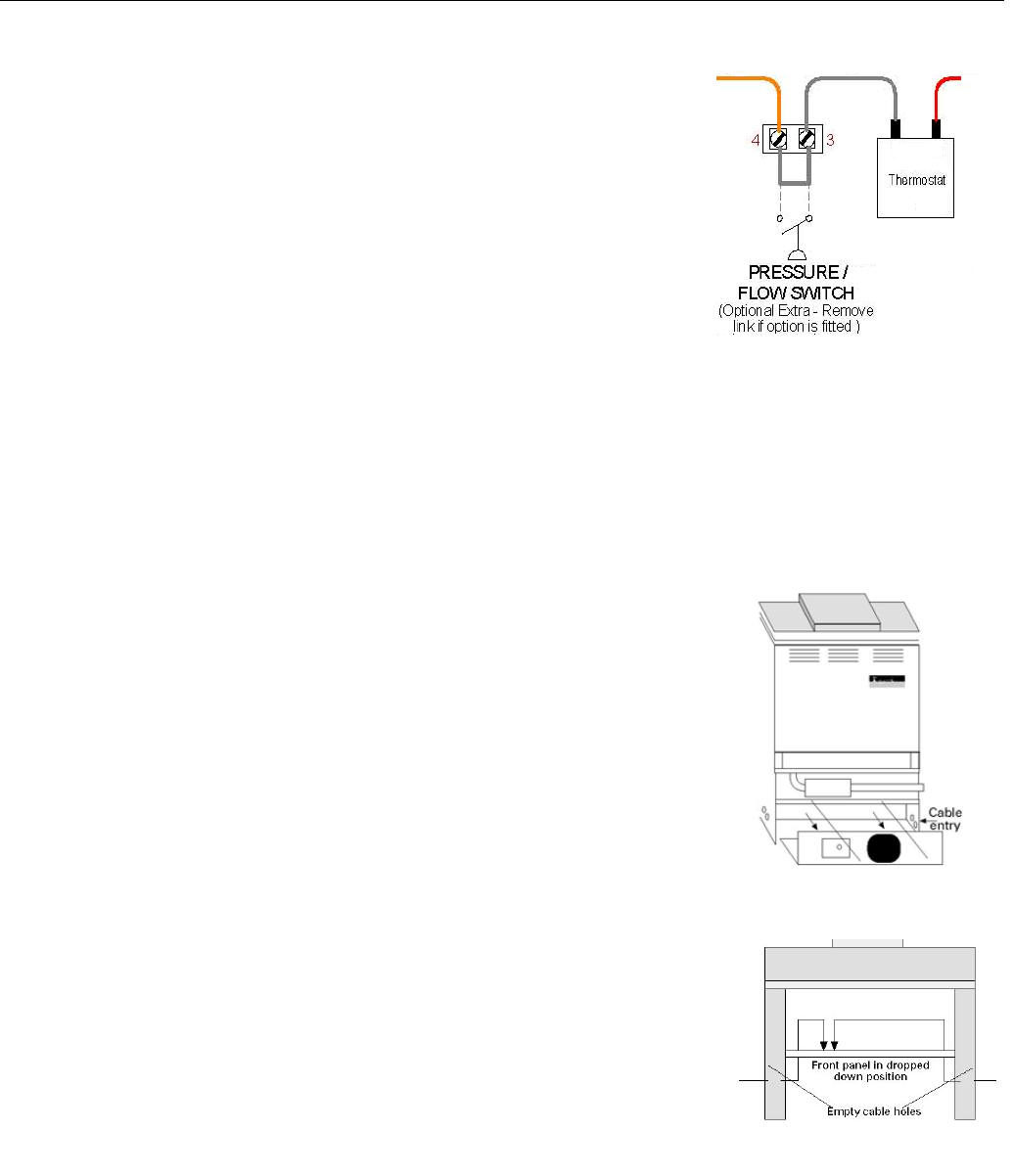
To connect a power flue to the water heater it is necessary to remove the
bridging wire between terminals 3 and 4 of the water heater terminal block and
connect the wiring to the power flue across these two terminals (refer to the
diagram opposite and to the wiring diagrams on pages 24 to 27).
BUILDING MANAGEMENT SYSTEM (BMS)
For applications requiring connection to a building management system, an optional BMS kit suitable for 147
On/Off models ONLY must be fitted to the water heater to provide ‘run’ and ‘fail’ status.
109 and 147 Hi/Lo models cannot be connected to a building management system.
CONTROL PANEL ACCESS
To access the electrical enclosure:
109 Models
• Remove the knurled screw from the centre of the lower front panel and pull out
at the bottom of the panel to remove.
• Remove the 8mm hex head screw from the centre of the electrical access panel.
• Slide the electrical access panel out.
147 Models
• Remove the lower front panel by lifting up and out.
• Remove 2 x Philips head screws (1 on each side) from the lower edge of the
control panel.
• Slide the control panel down and hinge out. NOTE: The control panel has tabs
fitted to support it on the water heater in the open position.
Control Box Electrical Access
147
Control Box Electrical Access
109


