22
CONNECTIONS – ELECTRICAL
All electrical work and permanent wiring must be carried out by a qualified person and in accordance with the
Wiring Rules AS/NZS 3000 and local authority requirements.
The water heater is supplied with a 1.8 metre lead and plug and requires a 240 V 50 Hz general purpose outlet
(GPO) to be located within 1.0 metre of the installation. NOTE: For outdoor installations the GPO must be
weatherproof. The GPO must be clear of the flue exhaust, draining water, gas supply pipe and water connections.
The water heater must be properly earthed and the installation of a Residual Current Device (RCD) is
recommended for added electrical safety
CAUTION: DO NOT LOCATE CABLES IN FRONT OF OR UNDERNEATH THE BURNER.
Where conduit is mounted to the water heater a 10mm air gap must be maintained from the water heater casing to
eliminate possible overheating. DO NOT locate conduits or cables where they will obstruct or restrict removal of
panels, access doors etc.
The water heater must NOT be able to operate without the pump running.
The water heater and pump may be supplied from the same electrical circuit, alternatively the 240 volt supply to the
water heater may be provided via auxiliary contacts of the pump contactor or relay (if fitted).
Where additional control wiring is connected to the water heater, which is not isolated by the GPO, a suitable
warning label must be affixed to the water heater identifying the isolation point for that particular wiring (e.g. by
circuit breaker or fuse number and switchboard identification number or location).
THERMOSTAT SETTING
The thermostat is adjustable; the range varies according to the
capacity and operation type (refer to the table opposite).
For reasons of safety and economy, we recommend that the thermostat is set at the lowest temperature that will
provide sufficient hot water. Discuss the thermostat setting requirements with the householder or responsible
officer. Refer to “Temperature Control”
on page 35.
INTERMITTENT PUMP OPERATION
For applications utilising intermittent pump operation a pump run on timer is fitted as standard equipment to the
water heater and must be utilised to prevent nuisance tripping of the high limit thermostat due to heat build up in
the heat exchanger. The timer should be set to allow the pump to operate for at least ten (10) minutes.
EXTERNAL CONTROLS
The water heater can be wired for use with an external flow switch, remote control thermostat or a remote time
switch.
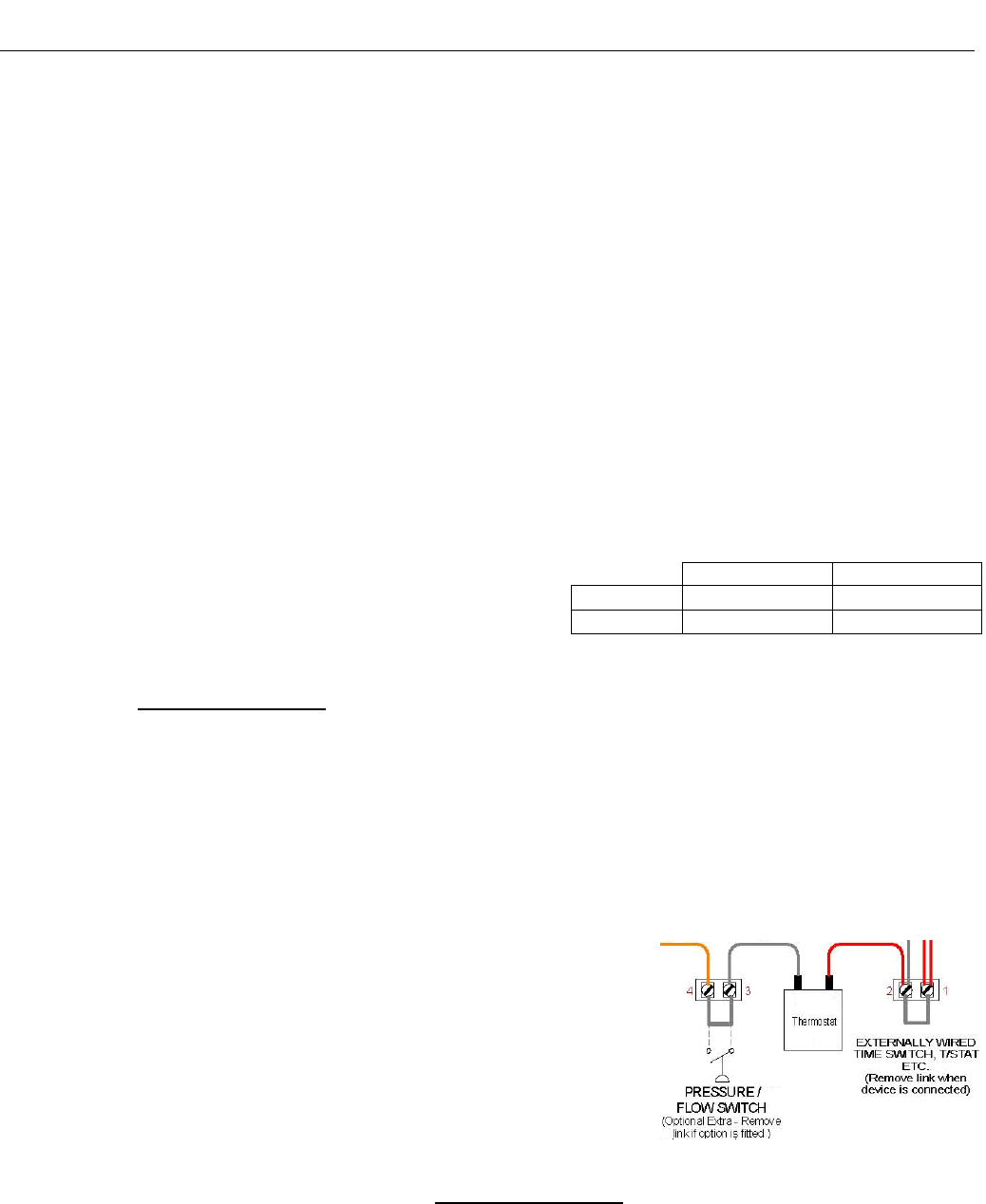
To connect an external switch, time clock or thermostat to the water heater
it is necessary to remove the bridging wire between terminals 1 and 2 of the
water heater terminal block and connect the external control across these
two terminals(refer to the diagram opposite and to the wiring diagrams on
pages 24 to 27).
To connect a flow switch to the water heater it is necessary to remove the
bridging wire from between terminals 3 and 4 of the water heater terminal
block and connect the flow switch across these two terminals (refer to the
diagram opposite and to the wiring diagrams on pages 24 to 27).
Where an external thermostat is utilised the water heater thermostat should be adjusted to a temperature higher
than the setting on the remote thermostat (Refer to "Temperature Control"
on page 35.
On/Off Hi/Lo
109
25°C - 95°C 45°C - 85°C
147
20°C - 80°C 0°C - 95°C


