2
Situate the pool heat pump carefully to minimize installation costs while providing maximum
efficiency of operation, and to allow adequate service access, as follows:
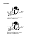
• For unrestricted air intake and service access, position each side of the unit at least 1 ft (30
cm) from walls, pipes and other obstructions.
• The unit is designed for outdoor installation; do NOT install it in an enclosed area such as a
shed or garage, unless ventilation is provided to ensure adequate air exchange for proper
operation. Recirculation of cold discharge air back into the evaporator coil will greatly
reduce the unit’s heating capacity and efficiency.
• This unit feature an ‘up-flow’ discharge for quiet operation. Air is pulled up through the
evaporator coil and discharged through the top grill. Allow at least 8 ft (2.4 m) clearance
above the unit for unrestricted air discharge. Do NOT install the unit under a porch or deck.
• To minimize water piping, locate the unit as close as possible to the existing pool pump and
filter.
• When installed in areas where freezing temperatures can be encountered, drain the water
circuit to prevent possible freeze-up damage. See Section IX, Freeze Protection.
II. Electrical Connections
The table below lists the typical electrical power requirements for your heat pump.
Refer to the unit rating plate below the control panel for precise power requirement for your unit,
and for ampacity and over-current protection requirements.
All wiring must be in accordance with the National Electrical Code, NFPA No. 70, latest edition,
and all applicable state and local codes.
NOTE: Refer to the National Electrical Code, Article 680, for general requirements
for swimming pools and equipment, and to Article 440 for special considerations
necessary for circuits supplying hermetic refrigeration motor/compressors.
This unit is pre-wired to work with external control systems, heat-on-demand options and other
external time clock overrides. Refer to the external control system’s instructions for installation
information.
Table 1: Typical System Electrical Power Requirements
Model VIN - Phase - Hz Min. circuit Ampacity (A) Max. breaker size (A)
5300 208/230 - 1 - 60 37 60
6300 208/230 - 1 - 60 36.9 60
8300 208/230 - 1 - 60
208/230 - 3 - 60
39.3
32.9
70
60


