


13
ate at maximum speed. Do not operate a summer
exhaust fan. Close fireplace dampers.
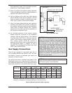
(d) Place in operation the appliance being inspected.
Follow the lighting instructions. Adjust tankstat so
appliance will operate continuously.
(e) Test for spillage at the draft hood relief opening
after 5 minutes of main burner operation. Use the
flame of a match or candle, or smoke from a ciga-
rette, cigar or pipe to visually check spillage.
(f) After it has been determined that each appliance
remaining connected to the common venting sys-
tem properly vents when tested as outlined above,
return doors, windows, exhaust fans, fireplace
dampers and any other gas burning appliance to
their previous conditions of use.
(g) Any improper operation of the common venting
system should be corrected so the installation
conforms with the latest edition of the National
Fuel Gas Code, ANSI Z223.1. When re-sizing any
portion of the common venting system, the com-
mon venting system should be re-sized to
approach the minimum size as determined using
the appropriate tables in Chapter 10 and in
Appendix G of the National Fuel Gas Code, ANSI
Z223.1 and CAN/CSA-B149.
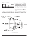
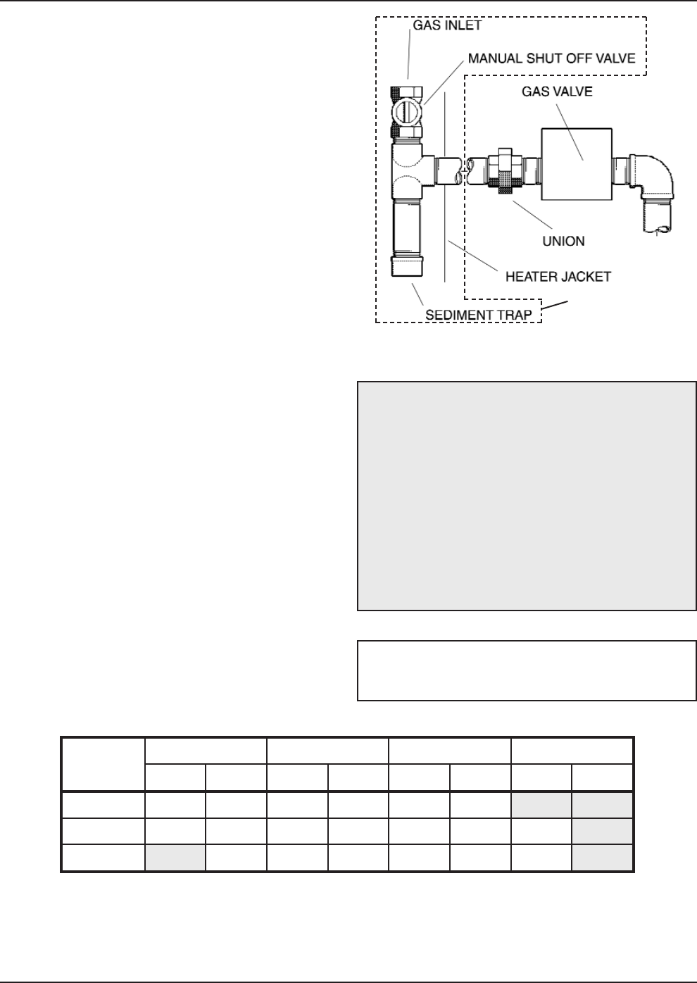
Gas Supply Connections
The inlet gas connection to the heater gas valve is
3/4" for models 260/261 and 330/331; and 1" for mod-
els 400/401. Provide an adequate gas supply line
according to Table G below.
Gas piping must have a sediment trap ahead of the
heater gas controls, and a manual shut-off valve locat-
ed outside the heater jacket. All gas piping should be
tested after installation in accordance with local codes.
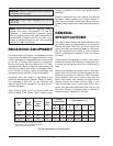
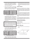
Model No.
3/4 in. 1 in. 1-1/4 in. 1-1/2 in.
Nat Pro Nat Pro Nat Pro Nat Pro
0260/0261 20 40 60 140 250 560
0330/0331 15 25 35 85 150 380 360
0400/0401 15 25 60 100 260 250
Natural gas, 1000 BTUH/ft .60 specific gravity @ 0.5 in. WC pressure drop.
Propane gas, 2500 BTUH/ft 1.53 specific gravity @ 0.6 in. WC pressure drop.
Table G: Maximum Equivalent Pipe Length (ft)
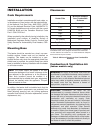
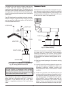
Fig. 12: Sediment Trap
CAUTION: The heater and its manual shut off
valve must be disconnected from the gas supply
during any pressure testing of that system at test
pressures in excess of 1/2 psi (3.45 kPa). Dissipate
test pressure in the gas supply line before
reconnecting the heater and its manual shut off valve
to gas supply line. FAILURE TO FOLLOW THIS
PROCEDURE MAY DAMAGE THE GAS VALVE.
OVER PRESSURED GAS VALVES ARE NOT
COVERED BY WARRANTY. The heater and its gas
connections shall be leak tested before placing the
appliance in operation. Use soapy water for leak test
DO NOT use open flame.
NOTE: Do not use teflon tape on gas line pipe
thread. A flexible sealant suitable for use with Natural
and Propane gases is recommended.
SUPPLIED BY
INSTALLER