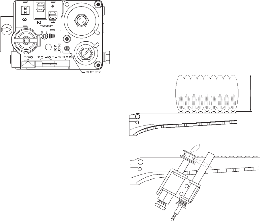
Pilot Adjustment
Fig.# 8935.0
ROBERTSHAW 7200 GAS VALVE
(Models 135 & 180)
e. Replace pilot adjustment cover screw, then
follow the lighting instructions to get heater
ready for operation.
FOR AUTOMATIC IGNITION SYSTEMS
A. Intermittent Ignition (IID)
1. Turn on power to the ignition systems and turn gas
supply off at the gas valve.
2. Check ignition module as follows:
a. Set the tankstat to high setting.
b. Watch for continuous spark at the pilot burner.
c. Time the spark operation. Time must be within
the lockout timing period (15 or 90 seconds).
d. Turn tankstat down to end call for heat and
wait 60 seconds on lockout models before
beginning step 3.
3. Turn on gas supply.
4. Set tankstat to high setting.
5. Systems should start as follows:
a. Spark will turn on and pilot gas valve will open
at once. Pilot burner should ignite after gas
reaches the pilot burner.
b. Spark ignition should cut off when pilot flame is
established.
c. Main gas valve should open and main burner
should ignite after gas reaches the burner port
FLAME FAILURE
With burner operating, close the manual fuel valves
to simulate a flame failure. System should lock out after
safety switch timing (15 seconds). After the safety
switch has cooled, open the manual valves (relight
standing pilots) and reset the safety switch; the burner
should restart.
INSPECTION PROCEDURES
BURNERS
Clean main burners and air louvers of dust, lint and
debris. Keep heater area clear and free from combus-
tibles and flammable liquids. Do not obstruct the flow of
combustion and ventilating air. Make visual check of
burner and pilot flame. Yellow flame indicates clogging
of air openings. Lifting or blowing flame indicates high
gas pressure. Low flame indicates low gas pressure.
Fig. #8144
MAIN BURNER FLAME
Fig. #8964
PILOT BURNER FLAME (STG PILOT UNITS)
NORMAL INSPECTION PROCEDURES
First and third month after initial start up and then on
an annual basis. If problems are found, refer to Trouble
Shooting Guide for additional directions.
1. Remove top of heater and inspect heat exchanger
for soot and examine venting system.
2. Remove rear header and inspect for scale depos-
its.
*3. Inspect pilot and main burner flame and firing rate.
*4. Inspect and operate all controls and gas valve.
*5. Visually inspect system for water leaks.
*6. Oil pump motor and bearing assembly, if oil cups
are provided.
7. Check flow switch paddle. (If provided)
8. Clean room air intake openings to assure adequate
flow of combustion and ventilation air.
9. Keep heater area clear and free from combustible
materials, gasoline, and other flammable vapors
and liquids.
*Should be checked monthly. (Takes approximately 15
minutes).
17
4"
Max.


