


4. SERVICING PROCEDURES
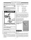
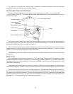
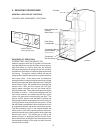
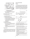
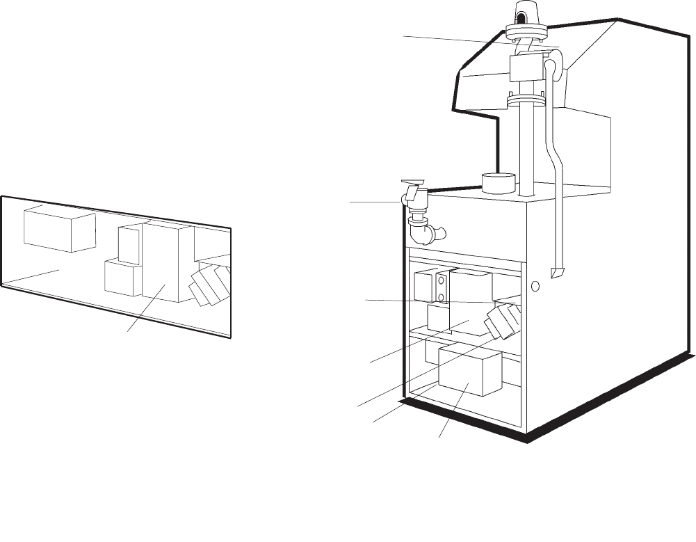
GENERAL LOCATION OF CONTROLS
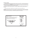
CONTROL BOX COMPONENT LOCATIONS
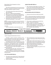
Ignition Module
(Auto Ignition Only)
13
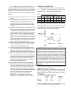
SEQUENCE OF OPERATION
INTERMITTENT IGNITION DEVICE (IID)
Heaters equipped with the IID system will automati-
cally light the pilot burner first and then the main burner,
each time there is a call for heat from the tankstat.
Whenever the tankstat is calling for heat, the circulator
supplied with the heater, will be energized and should
be running. The ignition control module will also be
energized to initiate the pilot ignition by opening the first
main valve (pilot). At the same time, the electronic
spark generator in the module produces a high voltage
spark pulse output that lights the pilot burner. If the pilot
burner does not light, the module will not energize the
second main valve and the burners will not light.
Ignition spark continues only until the timed trial for
ignition period ends. Then, the module goes into safety
shutdown or lockout. Lockout de-energizes the first
main valve operator and closes the first main (pilot)
valve in the gas control, stopping pilot gas flow. The
ignition control system must be reset by setting the
tankstat below water temperature for one minute or by
turning off power to the module for one minute. When
the pilot flame is established, flame rectification circuit
is completed between the sensor and burner ground.
The flame sensing circuit in the module detects the
flame current, shuts off the spark generator and ener-
gizes the second main valve operator which opens the
second main valve. This allows gas to flow to the
burners where it is ignited by the pilot burner flame.
When the tankstat is satisfied, the valve operators are
de-energized shutting off the pilot and main burners,
and also the circulator.
Fig.# 8195.3
Circulator
Manual Reset Limit
Pressure
Relief Valve
Field Wiring
Compartment
Temperature Sensor
Ignition Module
(Auto Ignition Only)
Transformer
Roll-Out Sensor
Gas Valve