


1. RECEIVING EQUIPMENT
On receipt of your equipment it is suggested that
you visually check for external damage to the carton. If
the carton is damaged, it is suggested that a note be
made on the Bill of Lading when signing for equipment.
Remove the boiler from the carton and if it is damaged
report the damage to the carrier immediately. Be
sure that you receive the number of packages indicated
on the Bill of Lading. Claims for shortages and
damages must be filed with carrier by consignee.
Purchased parts are subject to replacement only
under the manufacturer's warranty. Debits for defective
replacement parts will not be accepted and defective
parts will be replaced in kind only per our standard
warranties.
When ordering parts, you must specify Model and
Serial Number of boiler. When ordering under warranty
conditions, you must also specify date of installation.
Raypak recommends that this manual be re-
viewed thoroughly before installing your Raypak
Boiler. If there are any questions which this manual
does not answer, please contact your local Raypak
representative.
2. GENERAL SPECIFICATIONS
The Raypak hydronic boilers are design certified by
the American Gas Association, and tested under the
requirements of the American National Standard, ANSI
Z21.13. Each boiler has been constructed and pressure
tested in accordance with the requirements of Section
IV of the American Society of Mechanical Engineers
Code, and factory fire tested.
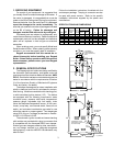
The boilers are designed for indoor installation with
a built-in drafthood, and a built-in sub-base for combus-
tible flooring. Models are available with standing pilot,
or with intermittent ignition device (I.I.D.). The boilers
are equipped with the following components: water
circulation pump, pressure relief valve, temperature/
pressure gauge, adjustable high limit switch, drain
valve, fast response temperature sensor, 40 VA trans-
former, pump relay, vent thermal switch, flame roll-out
switch, and redundant combination gas valve for use
with either natural or propane gases. Two-staged gas
valve (50% firing on 1st stage) is standard on models
H-0090, H-0135 and H-0180.
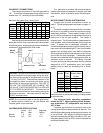
The automatic ignition models and some standing
pilot models are provided with a plug-in connector that
is compatible with the Honeywell D80D vent damper.
Similar type vent dampers made by other manufactur-
ers, and design certified by a nationally-recognized
testing Agency, under the ANSI Z21.66 standards, may
also be used.
Follow the installation instructions furnished with the
vent damper package. The plug-in connector can also
be used with power venters. Refer to the specific
installation instructions supplied by the power vent
manufacturer.
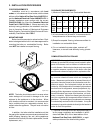
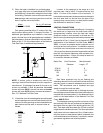
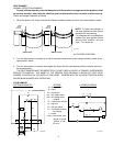
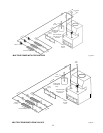
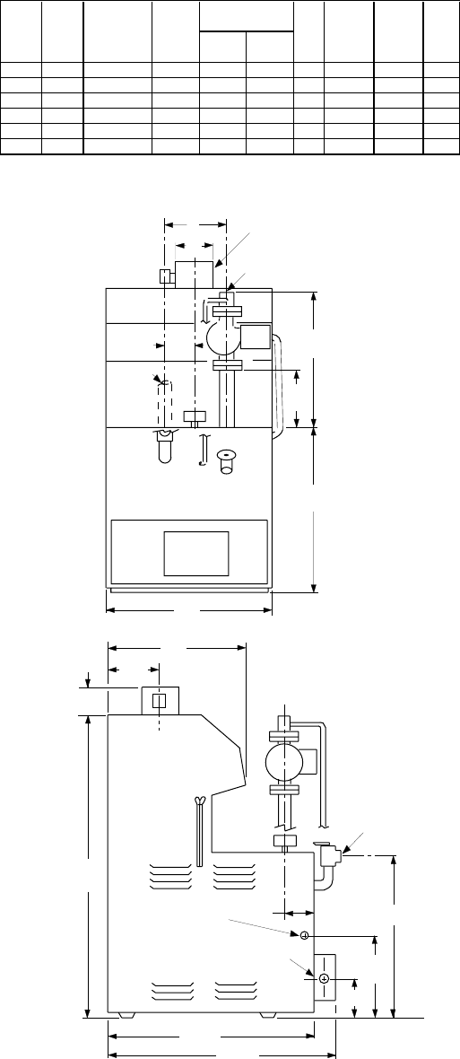
SPECIFICATIONS AND DIMENSIONS
3
K
16
4
1
/
2
33
1
/
4
22
1
/
8
12
1
/
2
5
18
3
1
/
4
26
1
/
2
C
THERMOSTAT CONN
(ELECTRICAL CONN
ON OTHER SIDE)
GAS
CONN
3/4 NPT PIPE
TO DRAIN
A
11
7
/
8
6
INLET
OUTLET
3
1
/
8
MIN
19
AUTOMATIC
VENT DAMPER
(FIELD INSTALLED)
B
HEATING NET K
INPUT CAPACITY I=B=R WATER GAS VENT
MODE
L
MBH MBH RATING NPT. NPT. A B C DIA.
H-0030 30 25 22 1" 1/2" 11" 5 3/4 5 1/2 4"
H-0042 42 35 30 1" 1/2" 11" 5 3/4 5 1/2 4"
H-0066 66 54 47 1" 1/2" 11" 5 3/4 5 3/4 5"
H-0090 90 74 64 1" 1/2" 11" 5 3/4 5 3/4 5"
H-0135 135 109 95 1 1/4" 1/2" 18" 6 1/4 6 1/4 6"
H-0180 180 148 129 1 1/4" 1/2" 18" 6 1/4 8.0 7"
CONNECTIONS
PIPING
Fig. #8978.1