


9
1. The heater must be provided with adequate sup-
ply of air for proper combustion and ventilation in
accordance with Sec. 5.3 of the latest edition of
the National Fuel Gas Code, ANSI Z223.1, or
applicable provisions of the local building codes.
2. If the heater room is located against an outside
wall and air openings can communicate directly
with the outdoors, the TWO openings on the out-
side wall must each have a net free area, in
square inches as shown in Table D.
Location of the openings is the same as in the pre-
vious case - that is, within 12 inches of the top,
and within 12 inches of the bottom of the enclo-
sure. If horizontal ducts are used, the area must
be doubled and the duct area shall not be less
than the area of the openings they connect, and in
no case shall the smallest dimension be less than
3 inches.
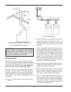
Venting Connections
Vent piping the same size or larger than the draft hood
outlet is recommended, however, when the total vent
height is at least ten (10) feet (draft hood relief open-
ing to vent terminal), the vent pipe size may be
reduced as specified in the National Fuel Gas Code,
ANSI Z 223.1. As much as possible avoid long hori-
zontal runs of vent pipe and too many elbows.
If installation requires horizontal runs, the vent pipe
must have a minimum of 1/4 inch per foot rise and
should be supported at not more than five foot inter-
vals. Plumbers tape, crisscrossed, will serve to space
both horizontal and vertical piping. Maximum vent con-
nector horizontal length shall be 1-1/2 feet (18 inches)
for each inch of connector diameter as shown in Table
E.
Gas vents supported only by the flashing and extend-
ing above the roof more than five feet should be
securely guyed or braced to withstand snow and wind
loads. We recommend use of insulated vent pipe
spacer through the roofs and walls.
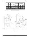
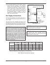
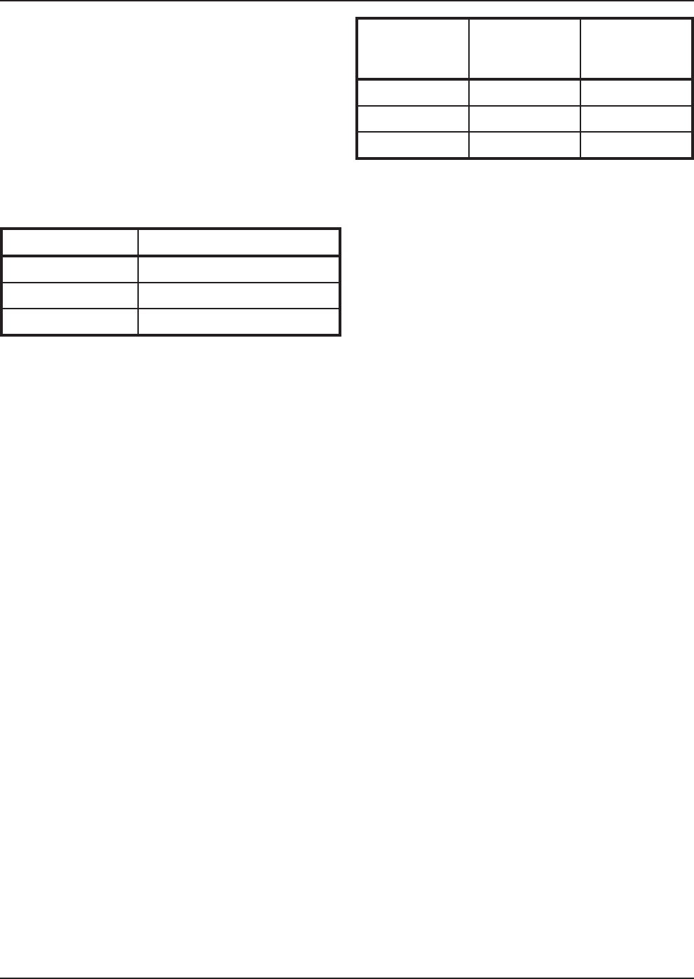
Model No. Sq. in. of Each Free Area
0090 24
0135 35
0195 50
Table D: Minimum Net Free Area
For protection against rain or blockage by snow, the
vent pipe must terminate with a listed vent cap which
complies with the local codes or, in the absence of
such codes, to the latest edition of the National Fuel
Gas Code, ANSI Z223.1.
The discharge opening must be a minimum of two feet
vertically from the roof surface and at least two(2) feet
higher than any part of the building within ten (10) feet.
Vent stack shall be at least five (5) feet in vertical
height above the drafthood outlet. The vent cap loca-
tion shall have a minimum clearance of four (4) feet
horizontally from, and in no case above or below,
unless a 4-foot horizontal distance is maintained, from
electric meters, gas meters regulators and relief equip-
ment.
The weight of the vent stack or chimney must not rest
on heater draft hood. Support must be provided in
compliance with applicable codes. The heater top and
draft hood must be readily removable for maintenance
and inspection. Vent pipe should be adequately sup-
ported to maintain proper clearances from combustible
construction.
Type "B" double wall or equivalent vent pipe is recom-
mended. However single wall metal vent pipe may be
used as specified in the latest edition of the National
Flue Gas Code ANSI Z223.1.
For connections to gas vents or chimneys, vent instal-
lations shall be in accordance with Part 7, Venting of
Equipment, of the National Fuel Gas Code, ANSI
Z223.1, or applicable provisions of the local building
codes.
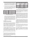
Model No.
Vent
Connector
Diameter (in.)
Max.
Horizontal
Length (ft)
0090 5 7.5
0135 6 9
0195 7 10.5
Table E: Vent Piping Specifications