


3
2.1 Operation Sequence
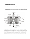
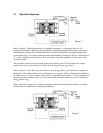
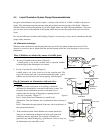
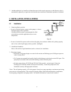
Refer to Figure 2. When pressurized air is supplied to chamber 'a' of the pump, bellows 'A' is
compressed and fluid is discharged from the bellows through the pump head discharge (outlet) port.
Simultaneously, bellows 'B' is extended and fluid is drawn into the bellows through the pump head
suction (inlet) port. Air is being exhausted from pump chamber 'b' during this process. When bellows
'B' is fully extended, proximity sensor 'B' is activated to signal the completion of this stroke to the
controller system.
The controller system receives the input signal from proximity sensor 'B' and changes the output
signal to the 4-way solenoid valve to switch it from the a
0
position to b
0
position.
Refer to Figure 3. Once the 4-way solenoid valve is in the b
0
position, pressurized air is supplied to
chamber 'b' of the pump and the process outlined above is reversed. Fluid is discharged from bellows
'B' while bellows 'A' is in its suction stroke and air is exhausted from chamber 'a.' Upon completion o
f
this pump stroke, proximity sensor 'A' is activated and the controller signals the valve to switch from
the b
0
position to a
0
.
With a constant air supply, this sequence is repeated continuously and the pump achieves a constant
flowrate based on installation and operating conditions.
Figure 2
Figure 3