


7
HEAT EXCHANGER
The following information is only a general guideline and any installation is made at the risk of the
installer. No responsibility to Raritan Engineering Company, Inc. is to be presumed or implied from
these general instructions.
Two 3/4" NPT female threads are provided in the
heat exchanger for connection to hoses or piping
from engine cooling system. Because of the diver-
sity of marine cooling configurations, it is not
possible to provide universal installation instruc-
tions; the installer MUST follow the engine
manufacturer's recommendations.
NOTE: If heat exchanger is higher than engine
coolant pump, check with engine manufacturer
for allowable height of coolant lines.
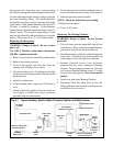
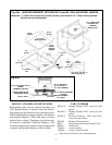
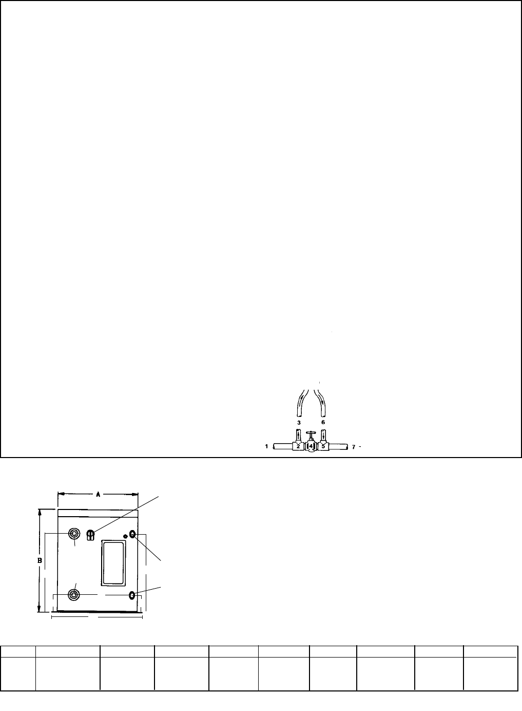
THE FOLLOWING DIAGRAM IS INTENDED ONLY AS A GENERAL GUIDELINE TO
SHOW HOW A PORTION OF THE ENGINE COOLANT MAY BE DIVERTED TO THE HEAT
EXCHANGER:
LEGEND:
1. Hottest water from engine (full flow).
2. Pipe tee; full flow on run, 3/4" NPT on branch.
3. Hose to hot water heat exchanger.
4. Gate valve sized to permit full flow of coolant.
5. Pipe tee; full flow on run, 3/4" NPT on branch.
6. Hose from hot water heat exchanger.
7. Full flow return to engine cooling system.
FROM WATER HEATER
(See Fig. #1)
TO WATER HEATER
To determine the proper setting of the gate valve
(4), the engine should be operated at full throttle
with the gate valve wide open. When the engine
temperature has stabilized, gradually close the valve
until the engine temperature begins to rise. The
valve should then be reopened enough to establish
the proper engine operating temperature. Engine
temperature should be monitored to verify that the
entire cooling system is functioning properly. Open
valve (4) if heated water temperature exceeds 120°
F (49°C).
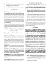
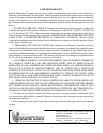
WARNING: Piping and gate
valve (Item #4) may become
extremely hot while engine is
operating. Be sure to wear
heavy gloves when adjusting
gate valve.
SPECIFICATIONS
Electrical Recovery Rate = 13 gallons (49.2 liters)
per hour
Maximum Operating Pressure:
Tank: rated at 150 psi (1034kPa)
With Temperature and Pressure Valve Installed:
50 psi (345kPa)
Amps: 10 (120V AC), 5 (240V AC) or
18.75 (240V AC) for model 17120203 and
17200203
Thermostat: Adjustable; Factory Set to 120°F (49°C)
Anode: Magnesium
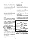
Model #
1706XX
1712XX
1720XX
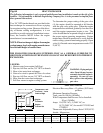
Size A B C D E F G Ship Wt.
6-gal(22.71liters) 14 ½"(36.9cm) 16 ¼"(41.3cm) 3 3/8"(8.6cm) 11"(28cm) 10 ¼"(26cm) 12 1/2"(31.8cm) 16 ½"(42cm) 37lbs(16.8kg)
12-gal(45.4 liters) 18 ¾"(47.6cm) 16 ¼"(41.3cm) 3 3/8"(8.6cm) 11"(28cm) 10 ¼"(26cm) 12 3/8"(31.4cm) 20 ½"(52cm) 55lbs(24.9kg)
20-gal(75.7 liters) 18 ¾"(47.6cm) 24 ¼"(61.6cm) 3 3/8"(8.6cm) 18 ¾"(47.6cm 10 ¼"(26cm) 12 3/8"(31.4cm) 20 ½"(52cm) 68lbs(30.8kg)
Engine
Coolant Out
Engine
Coolant In
Cold Water
In
Hot Water
Temperature and
Pressure Valve
Drain to Bilge
E
C
D
F
G
C
Fig. #4
XX = 01(120V) or 02(240V) without Heating Element, 11(120V) or 12(240V) with Heating Element
7