


4
2. Install a “tee” in the cold water supply line.
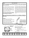
3. From the “tee” run a line to the heater, this line
MUST have a vacuum relief valve (such as
Watts Model N36) installed to prevent back
siphoning which could cause the tank to empty
and element to burn out (see Fig. #1). The
vacuum break must be mounted higher than the
hot water outlet from the water heater.
4. Connect this cold water supply line to the lower
heater connection marked COLD.
5. Installation of a drain valve between cold water
line and heater is recommended (see Fig. #1).
6. A two gallon expansion tank should be installed
in the cold water line to avoid pressure buildup
due to thermal expansion of water.
7. The upper heater connection, marked HOT, is
connected to the hot water faucets, shower, etc.
8. Secure all lines to the boat’s structure at frequent
intervals.
9. Be sure the safety relief valve is connected to
hose or piping so that overflow can run
unrestricted into the bilge and that a bilge pump
is in place. Any discharge from the hose must
exit within six inches above or any distance
below the structural floor and cannot contact
any live electrical part. The relief valve must
not be blocked off or reduced in size.
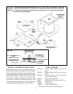
10. For models with heat exchangers see Fig. #4.
ELECTRICAL PREPARATION
All wiring should be done in accordance with
ABYC E8, AC wiring standard.
1. Install a 15 amp (10 amp for 240V AC or 20
amp for model #17120203 and 17200203)
Circuit Breaker in the 120V AC service line to
the water heater.
2. Use ONLY STRANDED #12-3 (#10-3 for
model #17120203 and 17200203) cable to the
heater. NEVER use solid (ROMEX-type) wire
on a boat; vessel vibration causes breakage due
to metal fatigue (see U.S. Coast Guard CFR
Title 33, Part 183.423).
3. Secure wire at intervals of 18" (45.7cm). Allow
about 24'' (61cm) of extra wire to make necessary
connections.
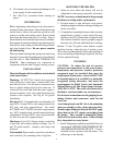
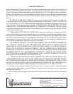
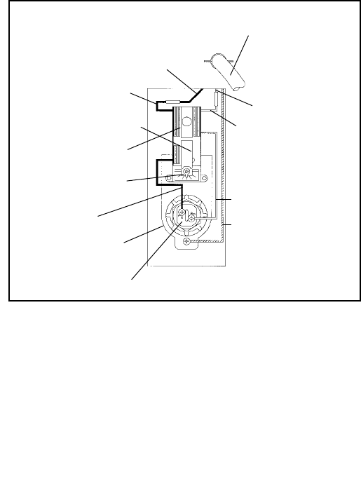
White
Black Service
Line (HOT)
Black Thermostat
Wire w/crimp
Connector
Red Reset Button
Continuous Ground
From Service Line
(Green)
White Service
Line (Neutral)
Thermostat Set
for 120
o
F (49°C)
Temperature
Adjustment
Black
Thermostat
Mounting Bracket
Connector
Electric Screw-In Heating Element
Fig. #2
Service Lines By
Installer 120V AC
(or 240V AC)
WIRING
WARNING: Before working on unit, be sure that
the circuit breaker is off.
1. Remove access panel.
2. Strip outer insulation off the cable (long enough
for green ground wire to reach Grounding Screw)
exposing three insulated wires.
3. Loosen strain relief connector by turning
counterclockwise and insert cable. Then expose
approximately 5/16" (8mm) of bare wire on each
of the three pieces of stranded wire.
4. Grounding: Join the AC Grounding Conductor
(green), using the crimp-on terminal end
(provided), to the screw at the bottom of the
Thermostat Bracket.
5. Attach black and white wires to Thermostat per
Fig. #2. Use crimp-on terminal ends (provided)
to ensure a secure installation. Do not use solder
as it will cause the wire to become solid rather
than stranded (making it susceptible to breakage
due to vibration).
6. Tighten strain relief by turning it clockwise.
CAUTION: To prevent burnout of heating
element do not turn on electricity. Follow start-up
procedure.
White Thermostat
Wire w/crimp
4