


Dolphin Basic Operation Instructions 5
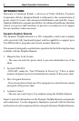
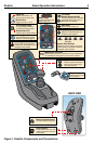
Figure 1. Dolphin Components and Connections
BACK VIEW
Battery Connection Socket
Connects to Battery Charger Plug.
DXBUS Sockets
Enables DXBUS cable to be used
to interconnect to the remainder of
the DX System.
Joystick
Controls the speed and direction of
power chair, as well as actuator
control when selected.
Magnetic Key
Used to lock and unlock
the DX System.
Battery Gauge
A series of ten LEDs, which
indicate charge level
On/Off Switch
Toggles the system on or off.
Status LED
Indicates On/Off Status, and
flashes to indicate system faults.
Drive Program Select Switch
This switch will scan through and
select one of five drive programs.
Hazard Light Switch & LED
Press to make both indicators flash
simultaneously. Press again to turn off.
LED flashes when activated.
Left & Right
Indicator Switches & LEDs
Press the appropriate switch to activate
turn indicator. Press again to turn off.
LED flashes when activated.
Horn Switch
Press to activate warning horn.
Light Switch & LED
Toggles the head/tail/side lights on or
off. LED is lit when activated.
Actuator Select Switches
5 switches for actuator selection. Not used for
actuator operation, only selection. LED above
switch lights up when activated.
Drive Program Display
A 7-segment display shows the
currently selected drive program.
Remote Status LED
Indicates status of Dolphin Remote.
seat height leg rest adjust
(right & left)
seat tiltback tilt
Magnetic Key Lock & LED
Locks DX System to prevent unauthorized use. Upon reactivation of
unit, LED will flash until magnetic key is used to unlock system.