


Page 44
7036-135G
November 22, 2011
R
Mt. Vernon Pellet Insert (AE)
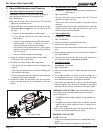
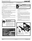
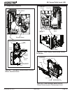
17. Power Supply
The power supply is located at the bottom left side of the
appliance. It converts 120 volt AC current to 15 volt DC current
to power the appliance.
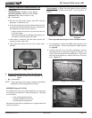
18.
Overheat Sensor (Snap Disc)
The overheat sensor is mounted on the back of the drop tube
in the center of the appliance and has a reset button. To
access it remove the right side panel. If the fi re tries to burn
back into the feed system or push exhaust up the feed tube,
this sensor will shut the appliance down, however the wall
control will continue to display messages. This sensor must
be manually reset. Disconnect power before resetting.
19. Thermocouple - Firepot
The thermocouple is located on top of the fi repot inside
the thermocouple cover (ceramic protection tube). The
thermocouple sends a millivolt signal to the control board
telling the control board there is a fi re in the fi repot.
20. Thermocouple on Drop Tube
The thermocouple is located on the bottom of the drop tube
on the right side and is attached with a wing nut. It turns
the convection blower on and off, varies the speed of the
convection blower and will shut down the appliance if internal
heat exceeds set temperature.
21. Vacuum Switch
The vacuum switch is located on the right side of the
appliance under the feed motor behind the right side panel
and connects to the drop tube with a hose. This switch turns
the feed system on when vacuum is present in the fi rebox.
The vacuum switch is a safety device designed to shut off
the feed motor if the exhaust or the heat exchanger system
is dirty or plugged or if the fi rebox door is open.
22. Wall Control Thermostat
The appliance is designed to run on a custom designed 3.3
volt DC thermostat wall control. It will not operate on any
other wall control. Refer to the instructions supplied with
the appliance located in the component packl.
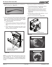
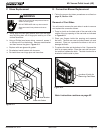
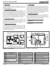
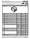
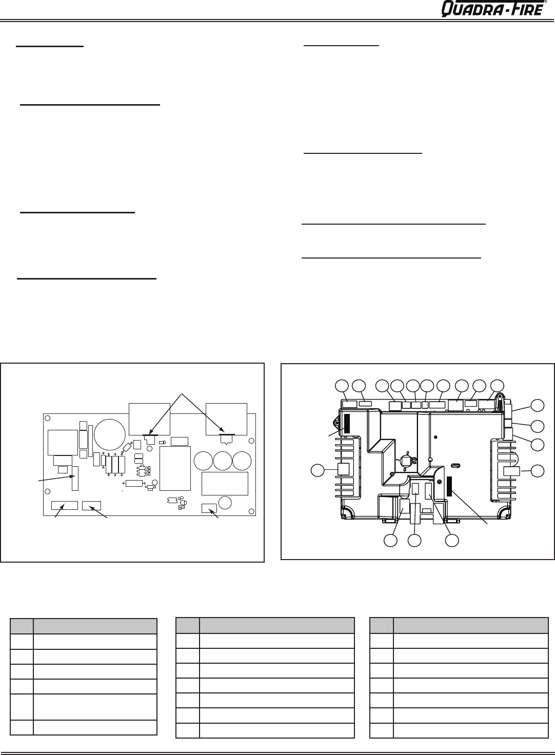
23. Wiring Connections for Power Supply
See Figure 44.1.
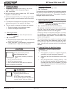
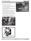
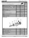
24. Wiring Connection for Control Board
See Figure 44.2.
Figure 44.2 - Control Board
Figure 44.1 - Power Supply
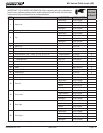
# Description
1 Combustion Blower
2 Auto-Clean System
3 Feed/Auger Motors
4 Hopper/Door Switches
5 Auger/Auto Clean/Vacuum
Switches
6 Low Fuel
# Description
7 Thermostat Wall Control
8 Combustion Blower (feedback)
9 Firepot Thermocouple
10 Drop Tube Thermocouple
n/a Not Used
11 Convection Blower (feedback)
n/a Not Used
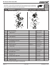
# Description
11 Convection Blower (feedback)
12 Igniter
13 AC Power In for Igniter
14 Convection Blower Power
15 Overheat Sensor (Snap Disc)
16 DC Power In from Power Supply
17 12 Volt Battery Back-up
17
1
2
3
4
5
6
7
8
9
10
11
12
13
14
15
16
n/a
Fuse 15A 120V,
under the cover
Fuse 15A 120V,
under the cover
Input Line Voltage
AC out to Control
Board
15V DC out to
Control Board
Fuse
15A 250V
Power Supply shown with cover removed
Input Line
Voltage
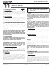
Heat sinks are taped to cover for shipping. Slowly lift cover
and cut the tape holding them in place and then you can
remove the cover.