


7
PV500-56 06/12
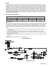
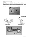
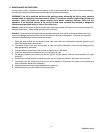
6.2 Gas Control Trains - All models include gas control trains with the following components: main manual
shutoff valve, two safety shutoff valves and pressure regulator. These components may be separate or two
or more may be combined in a common housing.
Caution: Do not adjust or remove any screws or bolts on gas train control components which are sealed
with a red or blue colored compound. Doing so will void all approvals and warranties.
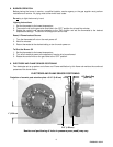
6.3 Inlet Pressure - Measure at the inlet pressure at the inlet pressure tap located on the upstream side (side
away from burner) on the top of the combination gas valve. The inlet pressure must remain within the
minimum and maximum values while the unit is at rest and while the unit is operating at maximum firing rate.
6.4 Manifold Pressure - Measure the manifold pressure at the manifold pressure tap located on top of the silver
elbow attached to the burner head. The rated manifold pressure appears on the burner data label located on
side of the burner control panel and is duplicated on the decal located near the front of the water heater.
6.5 Gas Service and Pipe Capacity - Before connecting the burner to the gas supply, insure that the gas pipes
and service meter are large enough to permit the additional load of the gas burner. (See Pipe Capacity
Table)
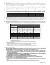
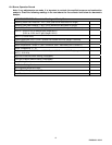
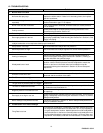
PipeCapacityforNaturalGasTable*(x1,000Btu/h’s)
PipeLength**
Nominaldiameterofpipeininches
1” 1 ¼” 1 ½” 2”
15’
345 750
30’
241 535 850
45’
199 435 700
60’
173 380 610
75’
155 345 545
90’
141 310 490
105’
131 285 450 920
120’
120 270 380 850
150’
109 242 300 780
180’
100 225 225 720
*Using0.6SpecificGravityGasandaPressureDropof0.3”ofWaterColumn
MultiplierforPropane:1.57
**Each90
0
elbowcountsas3’forthepurposeofthesecalculations
Pipe Capacity Example:
There is 75 feet of 1¼” pipe from the meter to the burner and there are 5 elbows.
(5 elbows X 3’) + 75’ pipe = 15’ + 75’ = 90’ of effective pipe length.
The maximum BTU that can be fired is 310,000 Btu/h. (See Pipe Capacity Table)
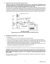
6.6 Gas Piping to Burner
All Piping Must Conform To Local Codes. Use black steel pipe and malleable iron fittings (do not use
cast iron parts) with a suitable pipe dope which is resistant to liquefied petroleum gases.
Safe operation of unit requires adequate gas supply with the required static and dynamic (flow)
pressures. Actual piping selection depends on many variables that must be carefully considered by the
gas piping system designer.
Do not select gas pipe sizes based only on the supplied tables. These tables are for use by the gas piping
system designer as a reference in checking pipe size selections.
The required gas pipe size may be larger than pipe connection size to the burner.
It is advisable to run a separate gas line from the meter to the gas burner to avoid pressure drops.
Installation of a union is suggested for ease of service.
Install a manual main gas shutoff valve, as specified by Code, approximately 6 feet (1.8 m) away from
unit.
A sediment trap (drip leg) MUST be provided in the inlet of the gas connection to the unit.
INLET PRESSURE NAT. GAS LP
Maximum Static Pressure (Inches-Water Column) 10.5" (2.62 kPa) 13" (3.24 kPa)
Minimum Flow Pressure (Inches-Water Column) 4.5" (1.21 kPa) 8" (1.99 kPa)