


6
PV500-56 06/12
4.4 Remote Air Consideration for Combined Remote Air Ducting
When remote air ducting is used, each water heater burner MUST have separate combustion air intake
piping.
5. VENTING
For appliances connecting to gas vents or chimneys, vent installation and vent size must be in accordance
with Part 7, "Venting of Equipment," of the latest edition of the National Fuel Gas Code, ANSI Z223.1, using
the “FAN” rating or, in Canada, Section 7, “Venting Systems and Air Supply for Appliances” of the latest
edition of the CAN/CSA B149 Installation Codes, or applicable provisions of the local building codes.
Suitable for use with Category I (non-positive vent static pressure, with a gas vent gas temperature that
avoids excessive condensate production in the vent) Type B gas vent systems with 1” (2.54 cm) minimum
clearance or Type L vent systems.
Vent should not be sized based only upon vent connection diameter at the burner.
Locate units as close as possible to chimney or gas vent. For conventionally vented installations, the
connection from the vent to the stack or vent termination outside the building must be made with listed
Type “B” double wall (or equivalent) vent connectors and must be direct as possible with no reduction in
diameter.
Support horizontal portions of the venting system to prevent sagging. Horizontal runs must slope upwards
not less than 1/4 inch per foot (21 mm/m) from the appliance to the vent terminal. Follow manufacturer’s
instructions.
Do not connect vent connectors serving this Category I, natural/negative draft vented, appliance to any
portion of a mechanical draft system operating under positive pressure.
Vent pressure must be between -.02" to -.06" W.C. (- 0.005 kPa to - 0.015 kPa) (Negative Pressure).
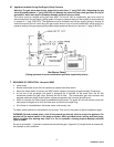
A barometric damper (draft control) is supplied for use on conventional vented installations. A properly
installed and adjusted barometric damper helps stabilize draft and regulate high updraft. Conventional
vented multiple unit installations with combined venting require barometric dampers to regulate draft at
each unit. Adjust the barometric damper to 0.04 inches water column (0.01 kPa) updraft. Follow the
barometric damper manufacturer’s installation instructions.
A listed vent terminal suitable for Category I products must be installed to adequately protect the gas
vent from wind and weather.
The vent terminal must extend at least 3 ft (.09 m) above the highest point where it passes through the
roof of a building and at least 2 ft (.06 m) higher than any portion of a building within a horizontal distance
of 10 ft. (3.0 m).
The vent cap must terminate at least 3 feet (0.91 m) above any forced air inlet within 10 feet (3.05 m); 4
feet (1.22 m) below, 4 feet (1.22 m) horizontally from or 1 foot (0.3 m) above any door, window or gravity
air inlet to the building; 1 foot (0.3 m) above grade, 1 foot (0.3 m) above normal snow levels and shall
terminate at least 7 feet (2.13 m) above grade when located adjacent to public walkways or gathering
areas.
The vent terminal must not be installed closer than 3 feet (0.91 m) from an inside corner of an L-shaped
structure.
6. GAS SUPPLY AND PIPING
Verify that the type of gas specified on rating plate is supplied to the unit. This unit is orificed for operation up
to 2000 feet (610 m) altitude. Appliance Btuh (kW) output derates 4% per 1000 feet (305 m) elevation above
sea level. Consult Factory for installations above 2000 feet ((610 m) elevation.
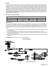
6.1 Gas Train and Controls Certification - NOTE: The gas train and controls assembly provided on this unit
have been tested under the applicable American National Standard to comply with safety and performance
criteria such as proper ignition, combustion and safety shutdown operation.