


PV 413A 8/05
START-UP OF POWER VT
®
WATER HEATERS OR BOILERS
**FOR DETAILED INFORMATION SEE INSTALLATION & MAINTENANCE MANUAL **
WARNING: These startup instructions are prepared for a qualified service installer, service
agency or gas supplier and require and rely on the experience and training of these
qualified gas appliance technicians to be safely completed. Attempting to follow these
instructions without such training and experience can result in property damage, exposure
to hazardous materials, personal injury or death.
1. Check the water heater tank to make sure it is full of water. (Remove air through T&P valve)
2. Remove enclosure panel cover on the water heater to expose control circuit. A wiring diagram, included in this
packet, will show the controls used in our circuitry.
3. Visually check that all components are intact and no damage has occurred during transit.
4. Check all connections within the control cabinet. A loose connection could cause intermittent shutdowns.
5. Check flue gases with an electronic flue analyzer to make final settings of gas pressure regulator.
6. The readings need to be taken from a hole in the vent several inches downstream of the fan outlet connection.
7. Insert 0-6" W.C. manometer into the test opening in the vent. Pressure in stack should not exceed 2" W.C.
8. When water in tank is above 120°F, insert analyzer or O
2
testing in test opening; take O
2
reading in percentage.
9. Increase manifold gas pressure at the main gas pressure regulator taking O
2
reading at each adjustment of gas
regulator until optimum O
2
% (5-7%) is reached. If O
2
% decreases, reduce the gas pressure to last reading
where the greatest reading is achieved.
10. CO should not exceed 200 ppm. A reading greater than 200 ppm indicates lack of air. Reduce manifold gas
pressure slightly and take readings until CO is within proper range. Optimum reading is no CO.
11. If manifold pressure was changed during startup, take a final CO and O
2
reading.
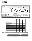
12. Record CO
2
and
NO
x
if applicable. (See I&M if NO
x
measurement is required).
13. Insert vent temperature gauge in test opening and read gross vent temperature; maximum gross stack is to be
250°F. If an excessively high gross vent temperature is recorded, consult the factory.
14. Check each operating and limit control to be sure they function properly by lowering and raising the temperature
setting on each of the controls, causing burner to cycle on and off.
15. NOTE: During the initial firing of the burner, smoke that is not related to the burner will be emitted from the
heater. This is normal during "burn in" and could possibly continue for several hours.
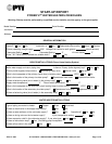
16. Complete the attached startup report.
Important – Contact PVI Customer Service, 800-433-5654, if any recommended setpoint or analysis
reading falls outside of the recommended ranges before completing startup.