QUICKDRAW
®
Steam Heater
6
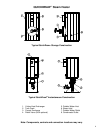
WATER INLET / OUTLET CONNECTIONS
Important: Do not use galvanized or steel pipe nipples when making waterside connections. Use
non-ferrous nipples only.
Make inlet and outlet water connections directly to the threaded bolt-on bronze tank flanges. Over tightening
connections to the flanges may cause damage to the flange or tank and are not covered by warranty. For
ease of service, install unions on inlet and outlet piping to the unit. Do not use galvanized nipples to make
tank connections as these will cause corrosion and rust. Piping and components connected to the water
heater must be suitable for potable water, for the water temperatures they will experience and for their
application.
CAUTION: Flush all water supply lines before connecting the unit.
FILLING THE UNIT
1.
Fill the system with water. To be sure that the unit is not “air bound,” open the relief valve. Leave the
valve open until a steady flow of water is observed. Close valve and complete filling the system.
2. In hard water areas, potable water treatment should be used to reduce introduction of minerals into the
system. Minerals in the water can collect on the tubes and heat-exchanger surfaces reducing the life of
the product. Heat exchanger failure due to scale accumulation is not covered by the product warranty.
3. Make sure there are no system leaks. DO NOT use petroleum based stop-leak products. All system
leaks must be repaired.
RELIEF VALVE PIPING
The water heater is supplied with a pressure and temperature relief valve, sized in accordance with ASME
requirements. Each relief valve should be piped to a suitable floor drain. No reducing coupling or other
restriction can be installed in the discharge line. It is strongly recommended that this valve should be
manually operating at least once a year.
WARNING: Make sure the safety relief valve is piped to a proper drain per instructions.
Scalding injury and/or water damage can occur from either the manual lifting of the lever or
the normal operation of the valve if it is not piped to a proper drain. Insure that the safety
relief valve piping is of the proper material and rating for the temperature and pressure of
the system and that it is secured to prevent possible injury. If the valve fails to flow water or
reseat, consult factory. The relief valve is a primary safety device.
STEAM & CONDENSATE CONNECTIONS
1. The condensate trap controls the discharge of condensate based on the load on the heat
exchanger, thus preventing the discharge of live steam through the unit. Appropriately sized traps
are available from your PVI representative.
2. Connect the steam supply to the steam inlet fitting on the unit. A Y-strainer (100 mesh stainless
steel sheet) must be installed ahead of the unit to prevent particles of scale and other solids from
damaging the seats of the steam valve. It is good practice to install a blowdown valve on the Y-
strainer piped to a suitable location that can be opened at intervals to clean the strainer screen. A
condensate trap may be located upstream of the steam valve. This trap will drain the condensate
that collects in the piping and must be plumbed to a suitable drain or the condensate receiver
plumbing.


