


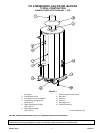

PV500-2 06/10 6 Section 2
MAINTENANCE AND SAFETY INSPECTIONS
To Minimize Scale Accumulation in Tank
1. A preventative maintenance program should be
established to assure a long, trouble-free life of the
water heater.
2. The tank should be flushed at two or three month
intervals depending on water conditions in your
location. To flush, turn off the electrical disconnect
switch to prevent the burner from operating. Open the
drain valve and allow water to flow through the tank
until it runs clear. Close the drain valve and turn the
electrical switch back on. Draining two or three
gallons from the bottom of the tank on a weekly basis
will also help prevent an accumulation of sediment.
Water impurities can consist of fine particles of soil or
sand which will settle out and form a layer of
sediment on the bottom of the tank.
A scale of lime will normally form in the tank during
operation and will accumulate on the bottom of the
tank. Lime is formed from the natural chemicals in the
water which precipitate out during the heating cycles.
Some water supplies contain more of these elements
than others, and the scale buildup will occur more
rapidly. Other factors affecting the scale buildup are
the amount of hot water used and the water
temperature. As more hot water is used, the more
fresh water containing the scale-forming elements is
brought into the tank. As the temperature of the water
increases, the rate of scale deposition will be
increased.
Sediment and scale accumulations in the tank will
greatly reduce the water heating ability of the heater
by reducing effectiveness of heat transfer surfaces.
When heating energy from the burner cannot be
effectively transferred to the water in the tank, the
metal can overheat causing it to lose structural
strength.
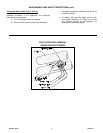
3. Should a firetube leak for any reason, consult the
factory for instructions. Inspect bottom tubesheet on a
regular basis to determine if insulation may have
pulled away from the tubesheet. Repair or replace as
required.
NOTE: Condensate coming from the tubes on a cold start
is normal and does not indicate a leaking tube.
4. The tank may have a handhole for inspection and
cleaning use. The handhole cover should be
periodically removed and the tank inspected for scale
buildup. If scale is present, it can be loosened with a
high-pressure stream of water. The smaller pieces
can be flushed through the drain and the larger
pieces removed by hand through the handhole. The
frequency of inspections should be determined by the
rate of scale buildup. We recommend 30-60 day
intervals.
Periodic Inspection of Operational Components
Periodic inspections and check-out of the burner
ignition system, control system and gas valve
operation should be made and recorded for future
reference.
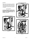
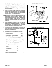
1. Pilot assemblies should be checked by a qualified
serviceman using control manufacturer's instructions.
Wiring connections on the ignition high voltage wire
and flame sensor wire must be tight. Clearance
between these wires and metal parts of the water
heater or burner must be maintained to avoid possible
shorting out. Positions of the electrode, flame sensor
and pilot flames are very important and have been set
by the manufacturer. If they are loose or if ceramic
insulators are cracked or broken, replace the pilot
assembly. To replace, remove pilot bracket from
bottom of burner, disconnect the pilot gas line and
replace pilot assembly on pilot bracket. Replace in
reverse order. Do not bend or distort pilot bracket as
this determines pilot flame position relative to burner
orifices. (See Figure 2-7). Inspect individual burner
jets for evidence of overheating. Replace burner jets
as necessary.
2. Examine the venting system at least quarterly for
proper connections, alignment and the presence of
corrosion. Any corroded vent section should be
immediately replaced to prevent CO leakage. Re-
check vent temperature (step 6, page 5) and correct if
necessary.
CAUTION: THE RELIEF VALVE IS A PRIMARY
SAFETY DEVICE.
3. The temperature and pressure relief valve should be
removed and inspected at regular intervals to
determine its condition for safe operation. The
openings inside the valve may become restricted by a
buildup of scale and become inoperative. If the valve
does not open and close properly when tested, it
must be replaced with a like kind or one meeting the
requirements stated on the rating tag located on the
relief valve.
4. Spark ignition system operation should be checked as
follows:
Flame failure – Close downstream gas train shutoff
valve and determine safety shutdown timing.
Flame signal – Determine flame signal strength in
accordance with step 7 on page 5.