


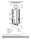

PV500-2 06/10 3 Section 2
START-UP PROCEDURES AND OPERATION
1. Some PVI atmospheric gas-fired water heaters are
designed to operate with a flue damper that is
shipped with the water heater for installation in the
field. If your water heater was shipped with a flue
damper, it must be attached to the flue collector and
interconnected to the ignition control module before
proceeding with start-up.
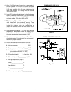
Flue Damper Installation
a. Set the flue damper over the flue collector opening
and align the damper drive housing to the front of
the heater.
b. Secure the flue damper to the flue collector at three
locations using the fasteners provided.
c. Remove the damper drive housing cover, feed the
damper interconnect cable through the access hole
and attach the female connector to the four-pin
receptacle. Secure the access hole cover, check to
make sure the test switch is in the "NORMAL"
position, and reattach the damper driver housing
cover.
CAUTION: BE SURE THERE IS NO FOREIGN MATTER
IN THE DAMPER HOUSING BEFORE ATTACHING
THE DRAFT DIVERTER.
Draft Diverter Installation
The draft diverter (provided) is designed to mount on top
of the flue damper. Set the draft diverter on top of the flue
damper and secure in three locations using the fasteners
provided.
Venting
Type B galvanized vent pipe, of the same diameter as the
draft diverter outlet, must be installed to route combustion
products either to existing overhead breeching or to an
appropriate outside location.
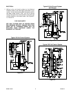
1. The control manufacturer's installation and service
manual and start-up procedures for the control
system on your water heater are shipped with the
unit. Study the information carefully and follow the
manufacturer's recommendations.
2. Fill the water heater tank with water. Open the relief
valve or a nearby hot water faucet to allow air in the
tank to escape. Be sure all connections into the tank
are tight as leaks at tank fittings will damage the
insulation.
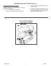
3. Remove the control box cover to access the control
thermostats and other electrical devices needed to
operate the water heater. The thermostats are labeled
as to their function. The temperature limiting device is
set at 200°F. The thermostats are factory set at
130°F. (the upper operating thermostat) and 120°F
(the operating thermostat). Adjustment may be made
by turning the thermostat dial to the desired
temperature.
CAUTION: BE SURE TO REATTACH THE
CONTROL BOX COVER TO HELP PREVENT
UNAUTHORIZED ACCESS TO CONTROLS.
CAUTION: DO NOT OVERTIGHTEN
COMPRESSION FITTINGS ON THERMOSTAT
BULBS AS CALIBRATION WILL BE CHANGED.
CAUTION: TEMPERATURES HIGHER THAN 125°F
INCREASE THE RISK OF SCALD INJURY!
Gas Train Safety Inspection
CAUTION: ALL VENTED GAS CONTROLS MUST
BE VENTED TO THE OUTSIDE USING TUBING
SIZED IN ACCORDANCE WITH THE
FOLLOWING TABLE:
V
ENT LINE SIZING
Fuel Line Size,
Nominal Pipe Size,
Inches
V
ent Line Size,
Nominal Pipe Size,
Inches
Up to 1 1/2 3/4
21
2 1/2 1 1/4
31 1/4
42
52
62 1/2
83