


PV500-2 06/10 1 Section 2
PVI ATMOSPHERIC GAS WATER HEATERS
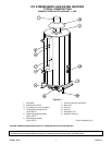
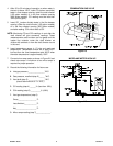
TYPICAL CONSTRUCTION
MANUFACTURED AFTER JANUARY 1, 1994
Figure 2-1
1. Vent stack * 7. Control switch(es) and fuse(s)
2. Draft diverter (hood) 8. Gas valve
3. Flue damper (on some models) 9. Pilot line
4. Temperature limiting device 10. Drip leg *
(set at 200°F) 11. Gas supply line *
5. Upper operating thermostat 12. Handhole cleanout
(set at 130°F)
6. Operating thermostat
(set at 120°F) (* Not furnished by PVI)
CAUTION: TEMPERATURES HIGHER THAN 125°F INCREASE THE RISK OF SCALD INJURY!
IMPORTANT: Clearances to unprotected combustible material must be 8" minimum at top, sides and rear, and 24" in front.
Clearances for servicing and inspection must be 18" minimum at sides and rear and 24" minimum in front.