


18
PV500-46U 06/12
9 VENTING
9.1 Venting the Power VT Plus “SANI” models:
Power VT Plus models with “SANI” in the model number are designed for operation only with stainless steel venting
listed by UL, ULC, ETL or CSA for Category IV, positive pressure, gas appliance venting. Installation requires a field
supplied stainless steel adapter from the 6-5/8 female economizer outlet to the specific size (six inch minimum) and
model vent used. Follow the vent manufacturer’s instructions for installation, sealing, supporting and terminating
their vent system. Do not use plastic venting of any type on models with SANI in the model number. Do not use a
barometric damper with the Power VT Plus positive pressure vent.
WARNING: On Power VT Plus models with “SANI” in the model number, use only stainless steel venting
listed by a nationally recognized testing laboratory for Category IV, positive pressure, gas appliance
venting. Use of plastic pipe of any type or use of venting materials other than specified in these
instructions can result in failure of the venting system and/or exposure to carbon monoxide which can
result in property damage, personal injury or death.
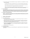
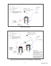
9.2 Venting the Power VT Plus:
The Power VT Plus (except models with “SANI” in the model number, see above) is designed for operation with a
"positive pressure vent system" constructed of locally obtained 6" or larger schedule 40 or 80 solid CPVC pipe. Do
not use CPVC pipe with cell/foam type construction (such as “CellCore”) or other non-solid CPVC plastic pipe.
Larger solid CPVC pipe may be substituted, however a solid CPVC increaser from 6” to the larger size must be
used for connection to the stainless steel 6-5/8” female flue outlet from the water heater economizer. Do not
insulate the plastic vent pipe. Stainless steel venting listed by UL, ULC, ETL or CSA for Category IV positive
pressure gas appliance venting may be used instead of CPVC plastic pipe venting. If such stainless steel venting is
used, follow the vent manufacturer’s instructions for installation, sealing, supporting and terminating their vent
system. Do not use a barometric damper with the Power VT Plus positive pressure vent.
WARNING: On Power VT Plus, (except models with “SANI” in the model number, see above) use only solid
CPVC pipe or stainless steel venting listed by a nationally recognized testing laboratory for Category IV
positive pressure gas appliance venting. Use of ABS pipe, CPVC pipe, pipe with cell/foam type
construction, plastic vent pipe other than solid CPVC or use of venting materials other than specified in
these instructions can result in failure of the venting system and/or exposure to carbon monoxide which
can result in property damage, personal injury or death.
WARNING: Do not vent this water heater into an existing or traditional gas vent or chimney or combine the
vent with any other appliance. Such venting could result in failure of the venting system and/or exposure to
carbon monoxide which can result in property damage, personal injury or death.
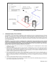
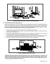
9.3 Maximum Category IV Vent Length (Equivalent Length)
A vertical or horizontal remote Category IV vent system must be used with this appliance. The maximum length of
field supplied Category IV vent is shown in the chart below titled Category IV Vent Equivalent Length.
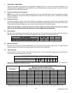
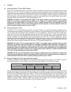
Maximum Category IV Vent Equivalent Length
Vent Size 6” Vent 7” Vent 8” Vent 9” Vent
Max Equivalent Length
100 feet 130 feet 250 feet 450 feet
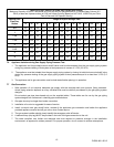
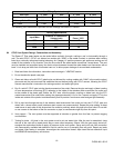
Pipe fittings reduce the maximum allowable vent length. Use the Category IV vent manufacturer’s equivalent length
deduction for all elbows, terminations, etc. If the information is not readily available from the vent manufacturer, use
the Vent Fitting Equivalent Length chart below to find the total equivalent length for all vent fittings in your
combustion air system. Then subtract this number of feet from the total equivalent length allowed in Maximum
Category IV Vent Equivalent Length chart above. The sum of this calculation is the maximum length of straight vent
allowed. If a longer length is required, repeat the calculation using a larger vent size. When using this chart, no
additional deduction is required for the addition of the vent system terminal.