


10
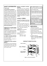
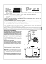
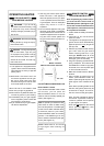
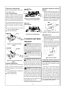
Make sure log sits flat on firebox floor.
IMPORTANT: Make sure log does not
cover any burner ports (see Figure 10).
Figure 9 - Checking Gas Joints
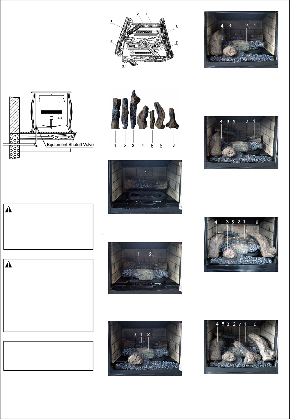
Figure 10- Installing Log Set
(Top View)
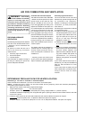
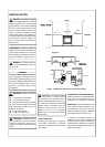
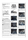
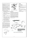
LOG PLACEMENT
FIG (3)
STEP 2: Install log 2 onto the two slots
in the middle plate.
FIG (1)
FIG (2)
STEP 1: Install log 1 onto the two slots
in the rear plate.
FIG (4)
STEP 3: Insert the two pins on the bot-
tom of log 3 into the two holes on fire-
box floor.
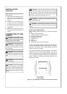
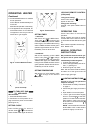
FIG (5)
STEP 4: Place log 4 on log 1 and log 3,
as shown.
Note: Log 4 will contact inside of
heater.
FIG (6)
STEP 5: Insert the recessed hole on
the bottom of log 5 onto the pin on log
1, with the other end of log 5 placed
on log 4, as shown.
FIG (7)
STEP 6: Place log 6 on log 1 and log
3.
Note: Log 6 will contact inside of
heater.
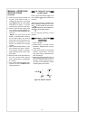
FIG (8)
STEP 7: Insert the recessed hole on
the bottom of log 7 onto the pin on log
2, with the other end placed on log 3.
It is very important to install the logs
exactly as instructed. Do not modify
logs. Only use logs supplied with
heater.
WARNING: Failure to position
the parts in accordance with these
diagrams or failure to use only parts
specifically approved with this heater
may result in property damage or
personal injury.
CAUTION: After installation and
periodically thereafter, check to en-
sure that no yellow flame comes in
contact with any log. With the heater
set to High, check to see if yellow
flames contact any log. If so, reposi-
tion logs according to the log instal-
lation instructions in this manual. Yel-
low flames contacting logs will cre-
ate soot.
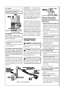
Pressure Testing Heater Gas
Connections
Continued
5. Correct all leaks at once.
6. Light heater (see Operating Heater).
Check all other internal joints for
leaks.
7. Turn off heater (see To Turn Off Gas
Appliance).