


9
IMPORTANT: Install equipment
shutoff valve in an accessible location.
The equipment shutoff valve is for turn-
ing on or shutting off the gas to the
appliance. Apply pipe joint sealant
lightly to male threads. This will pre-
vent excess sealant from going into
pipe. Excess sealant in pipe could re-
sult in clogged heater valves.
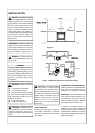
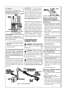
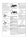
We recommend that you install a sedi-
ment trap in supply line as shown in
Figure 7. Locate sediment trap where
it is within reach for cleaning. Install in
piping system between fuel supply and
heater. Locate sediment trap where
trapped matter is not likely to freeze. A
sediment trap traps moisture and
contaminants. This keeps them from
going into heater controls. If sediment
trap is not installed or is installed
incorrectly, heater may not run properly.
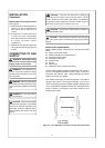
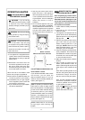
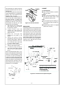
CHECKING GAS
CONNECTIONS
Figure 8 - Equipment Shutoff Valve
Pressure Testing Gas
Supply Piping System
Test Pressures In Excess Of 1/2
PSIG(3.5kPa)
1. Disconnect heater with its appliance
main gas valve (control valve) and
equipment shutoff valve from gas
supply piping system. Pressures in
excess of 1/2 PSIG will damage
heater regulator.
2. Cap off open end of gas pipe where
equipment shutoff valve was
connected.
3. Pressurize supply piping system by
either using compressed air or open-
ing gas supply tank valve.
4. Check all joints of gas supply piping
system. Apply mixture of liquid soap
and water to gas joints. Bubbles
forming show a leak.
5. Correct all leaks at once.
6. Reconnect heater and equipment
shutoff valve to gas supply. Check re-
connected fittings for leaks.
Test Pressures Equal To or Less
Than 1/2 PSIG(3.5 kPa)
1. Close equipment shutoff valve (see
Figure 8).
2. Pressurize supply piping system by
either using compressed air or open-
ing natural supply tank valve.
3. Check all joints from gas meter to
equipment shutoff valve (see Figure
9). Apply mixture of liquid soap and
water to gas joints. Bubbles forming
show a leak.
4. Correct all leaks at once.
Pressure Testing Heater
Gas Connections
1. Open equipment shutoff valve (see
Figure 8).
2. Open gas supply tank valve.
3. Make sure control knob of heater is in
the OFF position.
4. Check all joints from equipment
shutoff valve to control valve (see Fig-
ure 9). Apply mixture of liquid soap
and water to gas joints. Bubbles
forming show a leak.
CAUTION: Make sure external
regulator has been installed between
gas supply and heater. See guidelines
under Connecting to Gas Supply.
WARNING: Never use an open
flame to check for a leak. Apply a mix-
ture of liquid soap and water to all
joints. Bubbles forming show a leak.
Correct all leaks at once.
WARNING: Test all gas piping
and connections for leaks after install-
ing or servicing. Correct all
leaks at once.
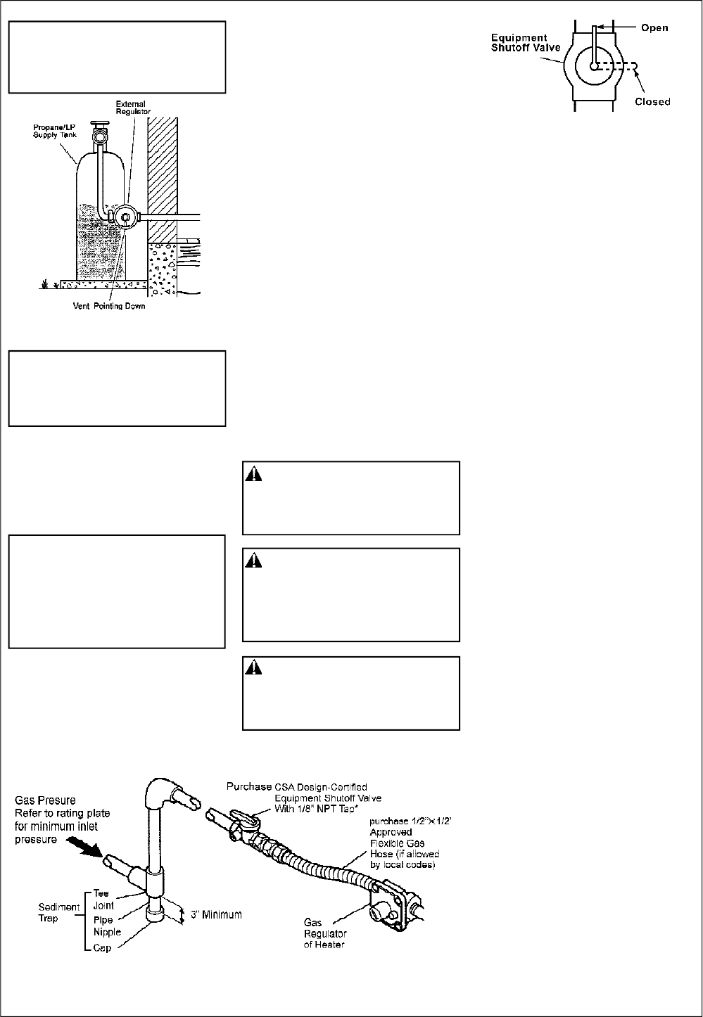
Figure 7 - Gas Connection
* Purchase the optional CSA design-
certified equipment shutoff valve from
your dealer.
** Minimum inlet pressure for purpose
of input adjustment.
In the State of Massachusetts the
gas cock must be a T handle type.
The State of Massachusetts re-
quires that a flexible appliance con-
nector cannot exceed three feet in
length.
Installation must include an equip-
ment shutoff valve, union, and plugged
1/8" NPT tap. Locate NPT tap within
reach for test gauge hook up. NPT tap
must be upstream from heater (see
Figure 7).
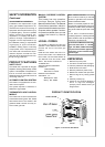
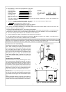
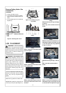
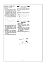
Figure 6 - External Regulator With
Vent Pointing Down
NG Models:
5”-10.5” W.C. supply pressure
Gas supplier provides external regu-
lator for natural gas.
LP Models:
11”-14” W.C. supply pressure
Gas supplier provides external
regulator for propane gas.